Rainbow Electronics MAX1641 User Manual
Page 11
configuration to PGND. These traces should be wide to
reduce resistance and as short as possible to reduce
stray inductance. All low-current ground paths should
be connected to GND. Place the input bypass capaci-
tor as close as possible to the IN pin. See MAX1640 EV
kit for layout example.
MAX1640/MAX1641
Adjustable-Output, Switch-Mode
Current Source with Synchronous Rectifier
___________________Chip Information
TRANSISTOR COUNT: 1233
QSOP.EPS
Maxim cannot assume responsibility for use of any circuitry other than circuitry entirely embodied in a Maxim product. No circuit patent licenses are
implied. Maxim reserves the right to change the circuitry and specifications without notice at any time.
Maxim Integrated Products, 120 San Gabriel Drive, Sunnyvale, CA 94086 408-737-7600 _____________________
11
© 2002 Maxim Integrated Products Printed USA is a registered trademark of Maxim Integrated Products.
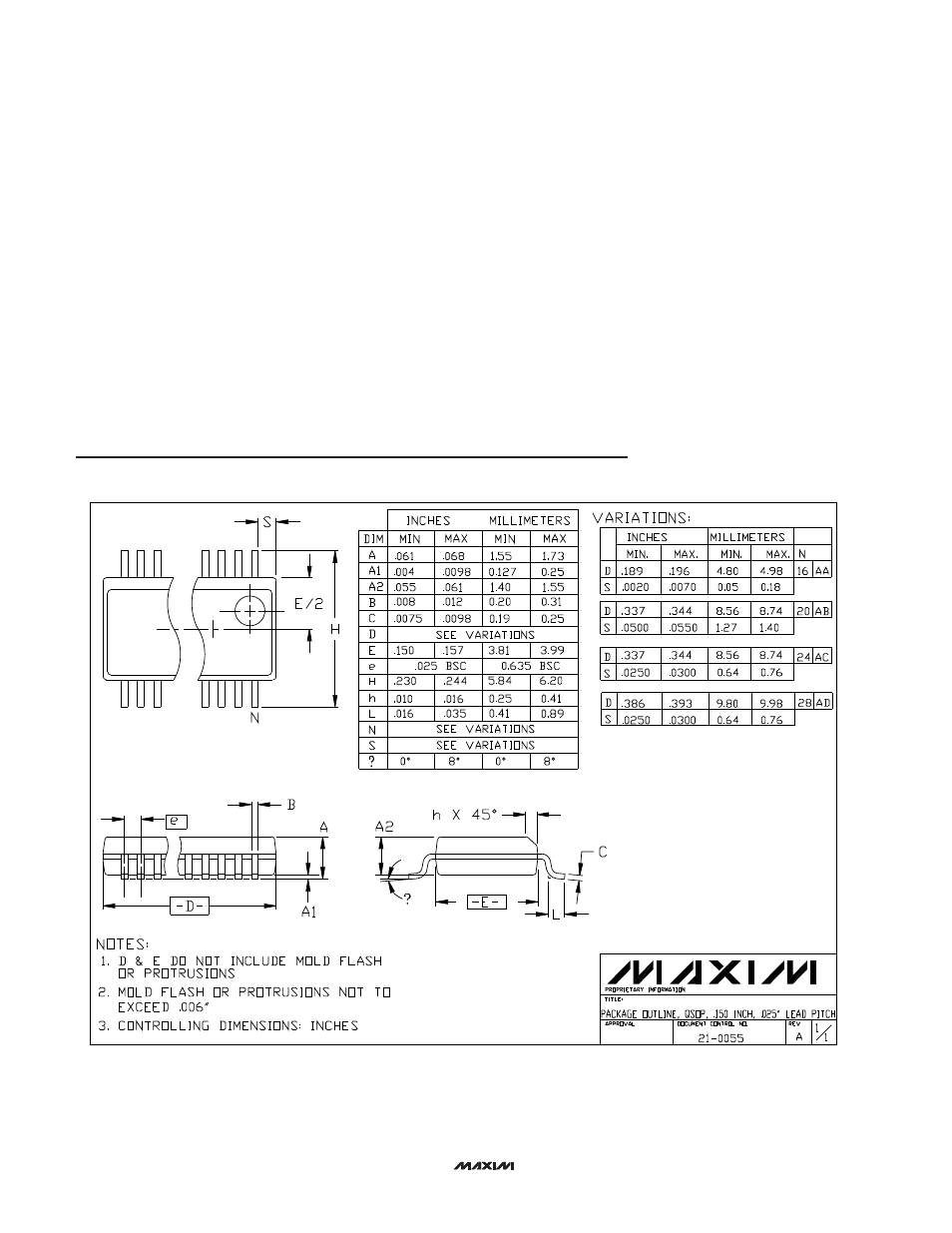
Package Information
(The package drawing(s) in this data sheet may not reflect the most current specifications. For the latest package outline information,
go to
www.maxim-ic.com/packages
.)