Rainbow Electronics MAX769 User Manual
Page 12
MAX769
2 or 3-Cell, Step-Up/Down,
Two-Way Pager System IC
12
______________________________________________________________________________________
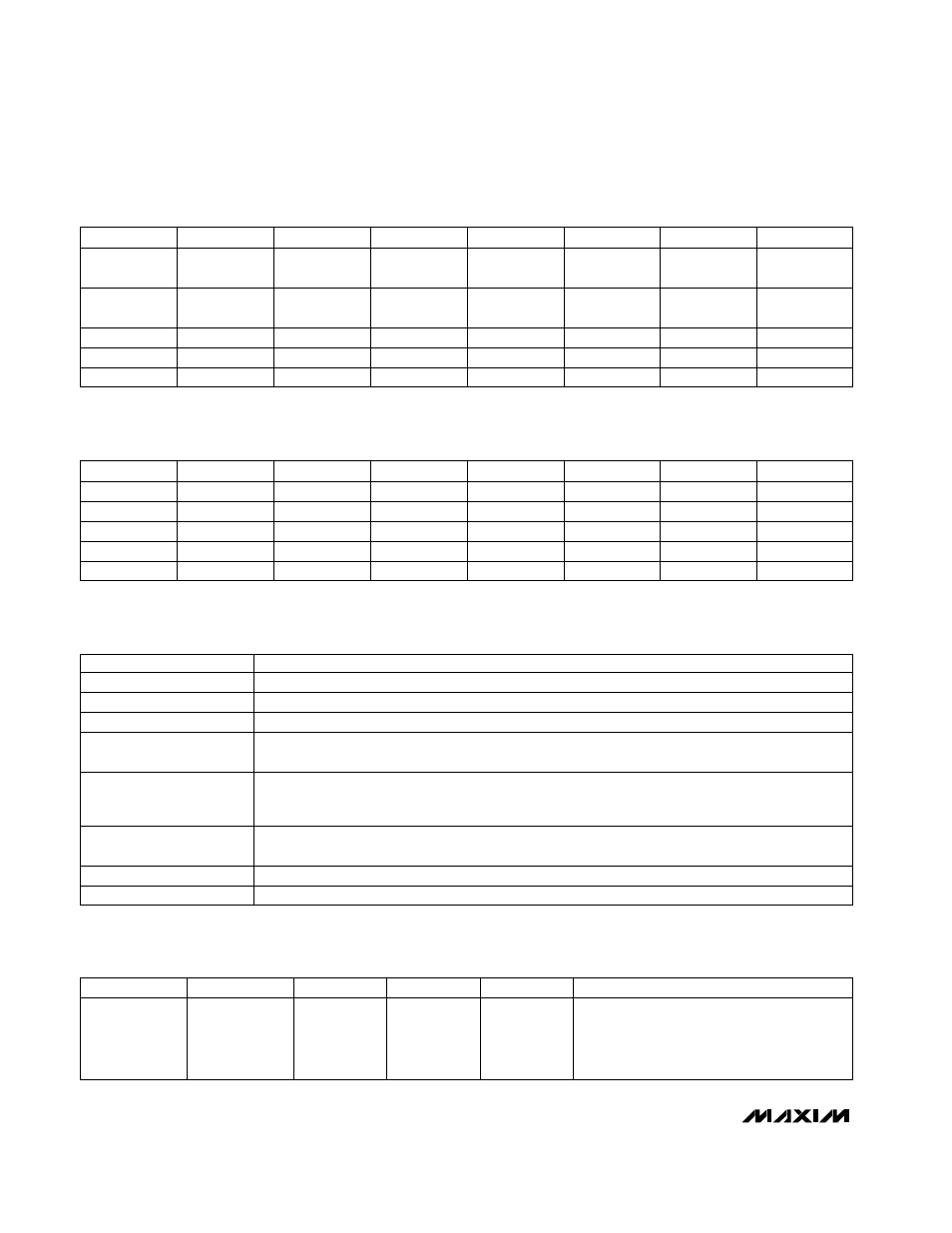
Table 1. Serial-Bit Assignments
Table 2. Serial-Bit Power-On Reset (POR) States
Table 3. Input-Bit Function Description
Table 4. Serial Output Data
R2 (MSB)
R0
D3
D1
0
0
DR1_ON
REG2_ON
0
1
LBO_Sets_
BACKUP
15mA_CHG
0
0
OV3
OV1
0
1
X
X
R1
0
0
1
1
D4
DR2_ON
X
OV4
X
D2
D0
RUN/
COAST
1mA_CHG
OV0
X
REG3_ON
BACKUP
OV2
X
1
DAC5
DAC3
DAC1
DAC6
DAC4
DAC0
DAC2
R2
R0
D3
D1
0
0
POR = 0
POR = 0
0
1
POR = 0
POR = 0
0
0
POR = 1
POR = 0
0
1
X
X
R1
0
0
1
1
D4
POR = 0
X
POR = 0
X
D2
D0
POR = 0
POR = 0
POR = 0
X
POR = 0
POR = 0
POR = 1
X
1
POR = 0
POR = 0
POR = 0
POR = 0
POR = 0
POR = 0
POR = 0
Sets 7-bit CH DAC voltage for A/D conversion (POR state is all zeros with DAC and comparators off).
DAC0–DAC6
Sets OUT Output Voltage (POR state is V
OUT
= 3.0V).
OV0–OV4
1 = Allows LBO to turn on the backup regulator and disable the DC-DC converter (POR state is no
connection between LBO and BACKUP).
LBO_Sets_BACKUP
1 = Turns on the backup linear regulator from NICD to OUT and disables the DC-DC converter (POR
state is BACKUP off). Setting this bit overrides 1mA_CHG, 15mA_CHG, and LBO_Sets_BACKUP
(Figure 1).
BACKUP
1 = Turns on the selected charge current to NICD. If both are set, the charge current is 15mA (POR
state is off).
1 = Turns on the selected switch (POR state is off).
1 = Turns on the selected regulator (POR state is off).
1 = Run Mode, 0 = Coast Mode (POR state is Coast Mode).
FUNCTION
1mA_CHG, 15mA_CHG
DR1, DR2
REG2_ON, REG3_ON
RUN/COAST
INPUT BIT
D7 (MSB)
D5
D3–D0
CH2_OUT
CH0_OUT
X
D6
CH1_OUT
D4
LBO
FUNCTION
CH_OUT and LBO output bits. A 1 indicates
that the selected channel (CH_) voltage is
greater than the CH DAC voltage or that LBI is
less than 0.6V.