Rainbow Electronics MAX769 User Manual
General description, Features, Applications
________________General Description
The MAX769 is a complete buck/boost power supply
and monitoring system for two-way pagers or other low-
power digital communications devices. Few external
components are required. Included on-chip are:
•
An 80mA output, synchronous-rectified, buck/boost
DC-DC converter with a digitally controlled +1.8V to
+4.9V output. The DC-DC converter is unique, since
it provides a regulated output for battery inputs that
are both less than and greater than the output volt-
age, without using transformers.
•
Three low-noise linear-regulator outputs
•
Three DAC-controlled comparators for software-
driven, 3-channel A/D conversion
•
SPI™-compatible serial interface
•
Reset and low-battery (LBO) warning outputs
•
Charger for NiCd/NiMH, lithium battery, or storage
capacitor for RF PA power or system backup
•
Two 1.8
Ω
(typical), serial-controlled, open-drain
MOSFET switches for beeper or vibrator drive
An evaluation kit for the MAX769 (MAX769EVKIT) is
available to aid in design and prototyping.
____________________________Features
♦
Regulated Step-Up/Step-Down Operation
♦
80mA Output from 3 Cells
♦
85% Efficiency
♦
13µA Idle Mode™ (coast) Current
♦
Selectable Low-Noise PWM or Low-Current PFM
Operation
♦
PWM Operating Frequency Synchronized to
Seven Times an External Clock Source
♦
Operates at 270kHz with No External Clock
♦
Automatic Backup-Battery Switchover
________________________Applications
Two-Way Pagers
GPS Receivers
2 or 3-Cell Powered, Hand-Held Equipment
MAX769
2 or 3-Cell, Step-Up/Down,
Two-Way Pager System IC
________________________________________________________________
Maxim Integrated Products
1
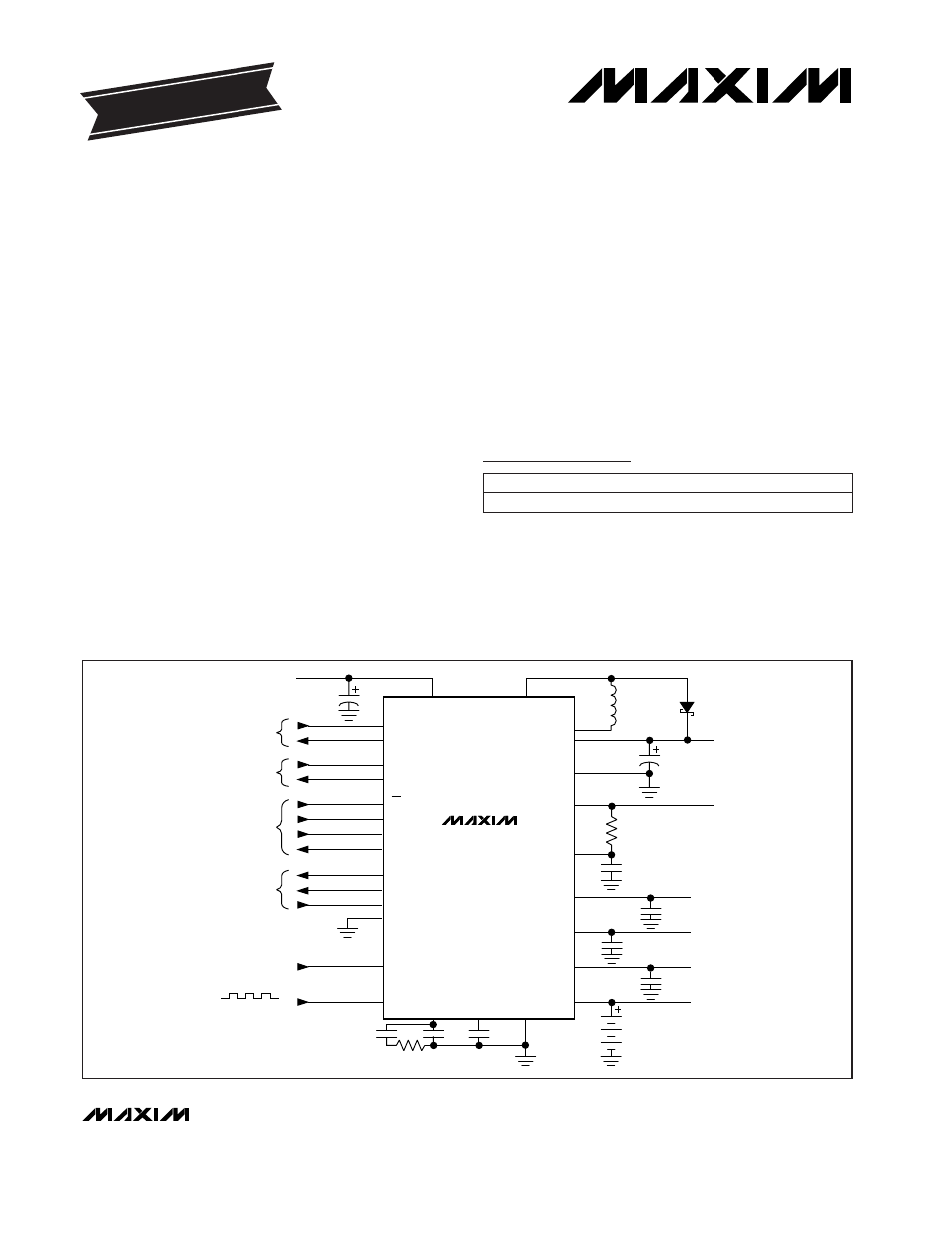
MAX769
INPUT
2 OR 3 AA ALKALINE BATTERIES
1.5V TO 5.5V
BATT
LX2
OUT
PGND
REG2IN
OFS
REG2
OUTPUT 2
2.85V ANALOG
LOW-BATTERY
IN/OUT
REJECT
IN/OUT
SERIAL
I/O
1.8
Ω
DRIVERS
A/D
INPUT
OPTIONAL
OUTPUT 1
3V LOGIC
OUTPUT 3
1V RECEIVER
TO RF PA
NiCd
BATTERY OR
STACK
REG1
REG3
NICD
AGND
REF
FILT
LBI
LBO
RSIN
RSO
CS
SCL
SD1
SD03
DR1
DR2
DR2IN
DRGND
CH0
SYNC
LX1
STORAGE
CAPACITOR
___________________________________________________Typical Operating Circuit
19-4771; Rev 1; 10/98
PART
MAX769EEI
-40°C to +85°C
TEMP. RANGE
PIN-PACKAGE
28 QSOP
Ordering Information
Idle Mode is a trademark of Maxim Integrated Products. SPI is a trademark of Motorola, Inc.
Pin Configuration appears at end of data sheet.
For free samples & the latest literature: http://www.maxim-ic.com, or phone 1-800-998-8800.
For small orders, phone 1-800-835-8769.
EVALUATION KIT MANUAL
FOLLOWS DATA SHEET