Rainbow Electronics DS2433 User Manual
Page 5
DS2433
5 of 21
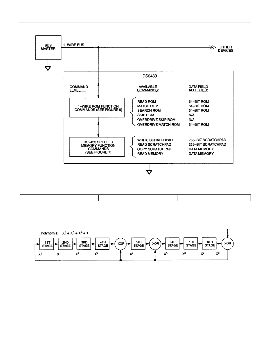
Figure 2. HIERARCHCAL STRUCTURE FOR 1-WIRE PROTOCOL
Figure 3. 64-BIT LASERED ROM
MSB
LSB
8-Bit CRC Code
48-Bit Serial Number
8-Bit Family Code (23h)
MSB
LSB MSB
LSB MSB
LSB
Figure 4. 1-WIRE CRC GENERATOR
MEMORY FUNCTION COMMANDS
The “Memory Function Flow Chart” (Figure 7) describes the protocols necessary for accessing the
memory. An example follows the flowchart. The communication between master and DS2433 takes place
either at regular speed (default, OD = 0) or at Overdrive Speed (OD = 1). If not explicitly set into the
Overdrive Mode the DS2433 assumes regular speed.
WRITE SCRATCHPAD COMMAND [0FH]
After issuing the write scratchpad command, the master must first provide the 2-byte target address,
followed by the data to be written to the scratchpad. The data will be written to the scratchpad starting at
the byte offset (T4:T0). The ending offset (E4:E0) will be the byte offset at which the master stops
INPUT
- MAX16840 (1 page)
- MAX9258 (54 pages)
- MAX66140 (21 pages)
- MAX9393 (14 pages)
- MAX66040 (25 pages)
- MAX6981 (1 page)
- MAX6965 (23 pages)
- MAX66100 (16 pages)
- MAX9135 (19 pages)
- MAX66020 (25 pages)
- MAX17127 (22 pages)
- MAX13175E (38 pages)
- MAX16820 (10 pages)
- MAX13237E (16 pages)
- MAX13483E (19 pages)
- MAX13362 (14 pages)
- MAX13486E (16 pages)
- MAX7311 (17 pages)
- MAX8759 (31 pages)
- SCAN92LV090 (13 pages)
- MAX6973 (23 pages)
- MAX13047E (14 pages)
- MAX16831 (20 pages)
- MAX14770E (15 pages)
- MAX11835 (1 page)
- MAX9621 (14 pages)
- MAX9217 (16 pages)
- MAX16841 (18 pages)
- MAX16834 (22 pages)
- MAX7315 (27 pages)
- MAX8645Y (15 pages)
- MAX6975 (23 pages)
- MAX6971 (12 pages)
- MAX3028 (21 pages)
- MAX9395 (13 pages)
- MAX7313 (27 pages)
- MAX6970 (1 page)
- MAX4821 (13 pages)
- MAX4895E (8 pages)
- MAX16823 (13 pages)
- MAX6963 (34 pages)
- MAX9216 (17 pages)
- MAX66000 (21 pages)
- MAX66120 (24 pages)
- MAX13223E (11 pages)