Figure 8. hardware configuration, Wire bus system, Hardware configuration – Rainbow Electronics DS2433 User Manual
Page 11: Transaction sequence
DS2433
11 of 21
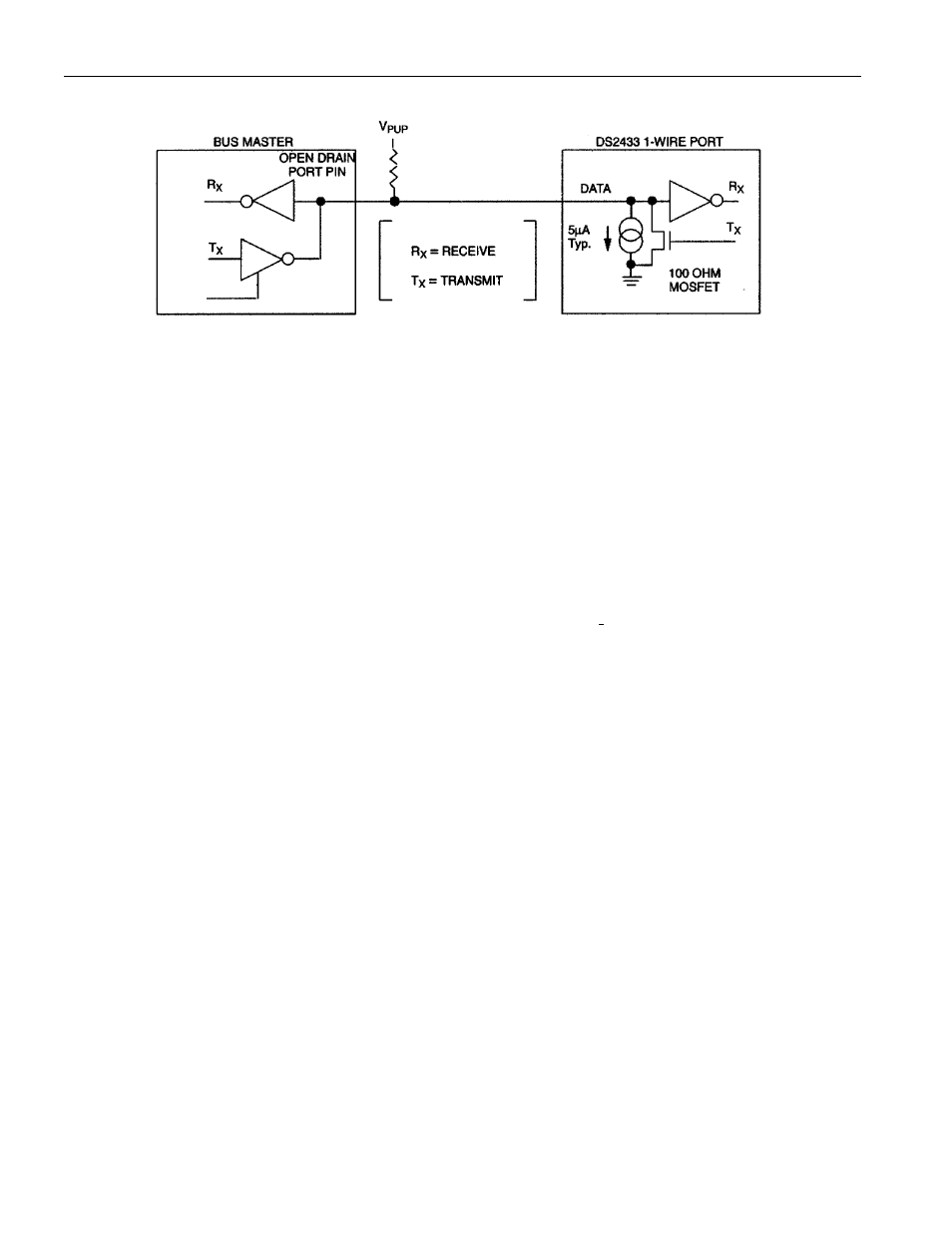
Figure 8. HARDWARE CONFIGURATION
*5k
W is adequate for reading the DS2433. To write to a single device, a 2.2kW resistor and V
PUP
of at
least 4.0V is sufficient. For writing multiple DS2433s simultaneously or operation at low V
PUP
, the R
PU
should be bypassed by a low-impedance pullup to V
PUP
while the device copies the scratchpad to
EEPROM. Depending on the 1-Wire communication speed and the bus-load characteristics, the optimal
pullup resistor (R
PU
) value will be in the 1.5k
W to 5kW range.
1-WIRE BUS SYSTEM
The 1-Wire bus is a system which has a single bus master and one or more slaves. In all instances the
DS2433 is a slave device. The bus master is typically a microcontroller. The discussion of this bus system
is broken down into three topics: hardware configuration, transaction sequence, and 1-Wire signaling
(signal types and timing). A 1-Wire protocol defines bus transactions in terms of the bus state during
specific time slots that are initiated on the falling edge of sync pulses from the bus master. For a more
detailed protocol description, refer to Chapter 4 of the Book of DS19xx iButton Standards.
HARDWARE CONFIGURATION
The 1-Wire bus has only a single line by definition; it is important that each device on the bus be able to
drive it at the appropriate time. To facilitate this, each device attached to the 1-Wire bus must have open
drain or 3-state outputs. The 1-Wire port of the DS2433 is open drain with an internal circuit equivalent
to that shown in Figure 8. A multidrop bus consists of a 1-Wire bus with multiple slaves attached. At
regular speed the 1-Wire bus has a maximum data rate of 16.3kbps. The speed can be boosted to 142kbps
by activating the Overdrive Mode. The 1-Wire bus requires a pullup resistor of approximately 5k
W.
The idle state for the 1-Wire bus is high. If for any reason a transaction needs to be suspended, the bus
MUST be left in the idle state if the transaction is to resume. If this does not occur and the bus is left low
for more than 16
ms (Overdrive Speed) or more than 120ms (regular speed), one or more devices on the
bus may be reset.
TRANSACTION SEQUENCE
The protocol for accessing the DS2433 via the 1-Wire port is as follows:
§ Initialization
§ ROM Function Command
§ Memory Function Command
§ Transaction/Data
R
PU
*