Pin description – Rainbow Electronics AT83C5127 User Manual
Page 4
4
AT83C5127
7519A–SCR–04/05
Pin Description
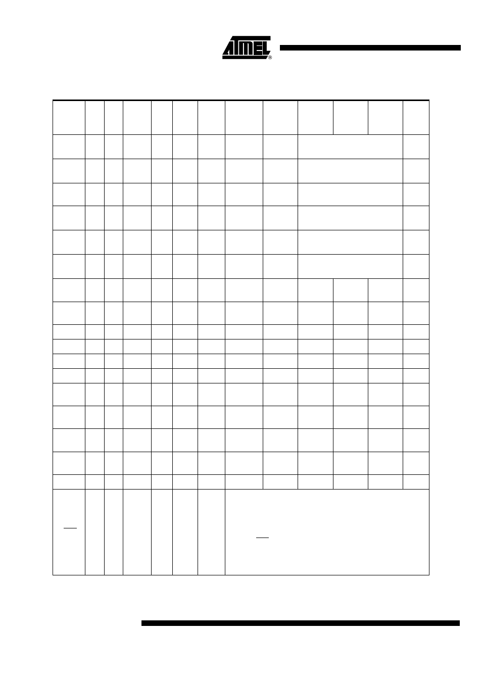
Table 1. Pin Description
Port
LQ
FP32
QF
N32
Internal
Power
Supply ESD
I/O
Reset
Level
Alt
Reset
Config
Conf 1
Conf 2
Conf 3
Led
CIO
32
32
CVCC
6KV
I/O
0
CIO
Port51
CVCC inactive at reset.
ESD tested with a 10µF on CVCC
CC4
3
3
CVCC
6KV
I/O
0
CC8
Port51
CVCC inactive at reset
ESD tested with a 10µF on CVCC
P1.2
2
2
VCC
2KV
I/O
1
CPRES
Port51
Weak & medium pull-up can be
disconnected
CC4
5
5
CVCC
6KV
I/O
0
CC4
Port51
CVCC inactive at reset
ESD tested with a 10µF on CVCC
CCLK
6
6
CVCC
6KV
O
0
CCLK
Push-pull
CVCC inactive at reset
ESD tested with a 10µF on CVCC
CRST
4
4
CVCC
6KV
O
0
CRST
Push-pull
CVCC inactive at reset
ESD tested with a 10µF on CVCC
P1.6
23
23
VCC
2KV
I/O
1
Port51
P1.7
31
31
VCC
2KV
I/O
1
CCLK1
Port51
P3.0
22
22
VCC
2KV
I/O
1
RxD
Port51
Push-pull
P3.1
24
24
VCC
2KV
I/O
1
TxD
Port51
Push-pull
P3.2
20
20
VCC
2KV
I/O
1
INT0
Port51
LED0
P3.3
19
19
VCC
2KV
I/O
1
INT1
Port51
Push-pull
P3.4
18
18
VCC
2KV
I/O
1
T0
Port51
Push-pull
LED1
P3.5
21
21
VCC
2KV
I/O
1
T1
Port51
P3.6
17
17
VCC
2KV
I/O
1
Port51
LED2
P3.7
13
13
VCC
2KV
I/O
1
Port51
LED3
P5.0
7
7
VCC
2KV
I/O
1
Port51
Push-pull
RST
16
16
VCC
I/0
Reset Input
The Port pins are driven to their reset conditions when a voltage lower
than V
IL
is applied, whether or not the oscillator is running.
This pin has an internal 10K pull-up resistor which allows the device to
be reset by connecting a capacitor between this pin and VSS.
Asserting RST when the chip is in Idle mode or Power-Down mode
returns the chip to normal operation.
The output is active for at least 12 oscillator periods when an internal
reset occurs.