Rainbow Electronics BA6209N User Manual
Page 5
390
Motor driver ICs
BA6209 / BA6209N
F
Circuit operation
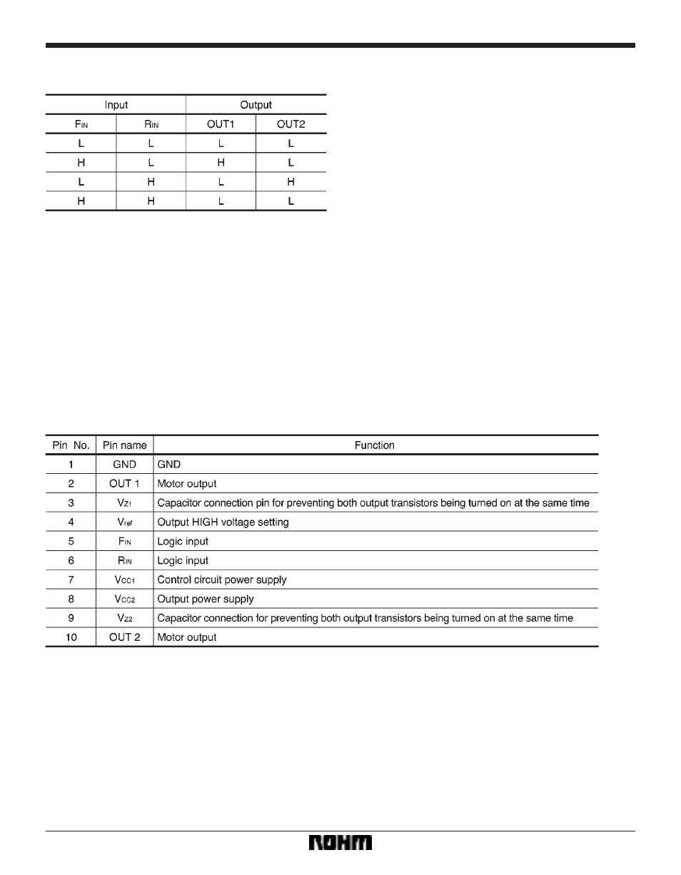
Input / output truth table
Forward / reverse control, forced stop, and rush current
absorption are controlled by the combination of F
IN
and
R
IN
input states.
(1)
Forward / reverse control circuit
When F
IN
is HIGH and R
IN
is LOW, current flows from
OUT1 to OUT2. When F
IN
is LOW and R
IN
is HIGH, cur-
rent flows from OUT2 to OUT1 (refer to the truth table).
(2)
Forced stop circuit
By setting R
IN
and F
IN
both HIGH or both LOW, power
supply to the motor is shut down and a brake is applied
by absorbing the motor counter-electromotive force.
(3)
Rush current absorption circuit
When a high voltage (caused by such as a motor rever-
sal) is generated on OUT1 and OUT2, an internal
comparator detects the high voltage and turns on an in-
ternal circuit that absorbs rush currents.
(4)
Drive circuit
The forward direction of the motor connected between
OUT1 and OUT2 corresponds to the current flow from
OUT1 to OUT2, and the reverse direction corresponds to
the current flow from OUT2 to OUT1. The output voltage
(V
OUT
) applied to the motor is given by the equation :
V
OUT
(V) = V
ZD
*
V
CE
(sat.) = V
ZD
*
0.2 (I
OUT
= 100mA)
where V
ZD
is the zener voltage of the constant voltage
diode (ZD) connected to pin 4.
If V
ref
is left OPEN, the output voltage (V
OUT
) is given by
the equation :
V
OUT
(V) = V
CC
1
*
V
CE
(sat.) (PNP)
*
2V
F
*
V
CE
(sat.)
= V
CC
1
*
1.8 (I
OUT
= 100mA)
F
Pin descriptions