Rainbow Electronics DS2761 User Manual
Page 7
DS2761
7 of 24
charge FET back on (unless another protection condition prevents it). Discharging remains enabled
during overvoltage, and the DS2761 re-enables the charge FET before V
IN
< V
CE
if a discharge current of
-80mA (V
IS
≤ -2mV) or less is detected.
Undervoltage. If the voltage of the cell drops below undervoltage threshold V
UV
for a period longer than
undervoltage delay t
UVD
, the DS2761 shuts off the charge and discharge FETs, sets the UV flag in the
protection register, and enters sleep mode. The DS2761 provides a current-limited recovery charge path
from PLS to V
DD
to gently charge severely depleted cells during sleep mode.
Overcurrent, Charge Direction. The voltage difference between the IS1 pin and the IS2 pin (V
IS
= V
IS1
-
V
IS2
) is the filtered voltage drop across the current-sense resistor. If V
IS
exceeds overcurrent threshold
V
OC
for a period longer than overcurrent delay t
OCD
, the DS2761 shuts off both external FETs and sets the
COC flag in the protection register. The charge current path is not re-established until the voltage on the
PLS pin drops below V
DD
- V
TP
. The DS2761 provides a test current of value I
TST
from PLS to V
SS
to pull
PLS down in order to detect the removal of the offending charge current source.
Overcurrent, Discharge Direction. If V
IS
is less than -V
OC
for a period longer than t
OCD
, the DS2761
shuts off the external discharge FET and sets the DOC flag in the protection register. The discharge
current path is not re-established until the voltage on PLS rises above V
DD
- V
TP
. The DS2761 provides a
test current of value I
TST
from V
DD
to PLS to pull PLS up in order to detect the removal of the offending
low-impedance load.
Short Circuit. If the voltage on the SNS pin with respect to V
SS
exceeds short-circuit threshold V
SC
for a
period longer than short-circuit delay t
SCD
, the DS2761 shuts off the external discharge FET and sets the
DOC flag in the protection register. The discharge current path is not re-established until the voltage on
PLS rises above V
DD
- V
TP
. The DS2761 provides a test current of value I
TST
from V
DD
to PLS to pull
PLS up in order to detect the removal of the short circuit.
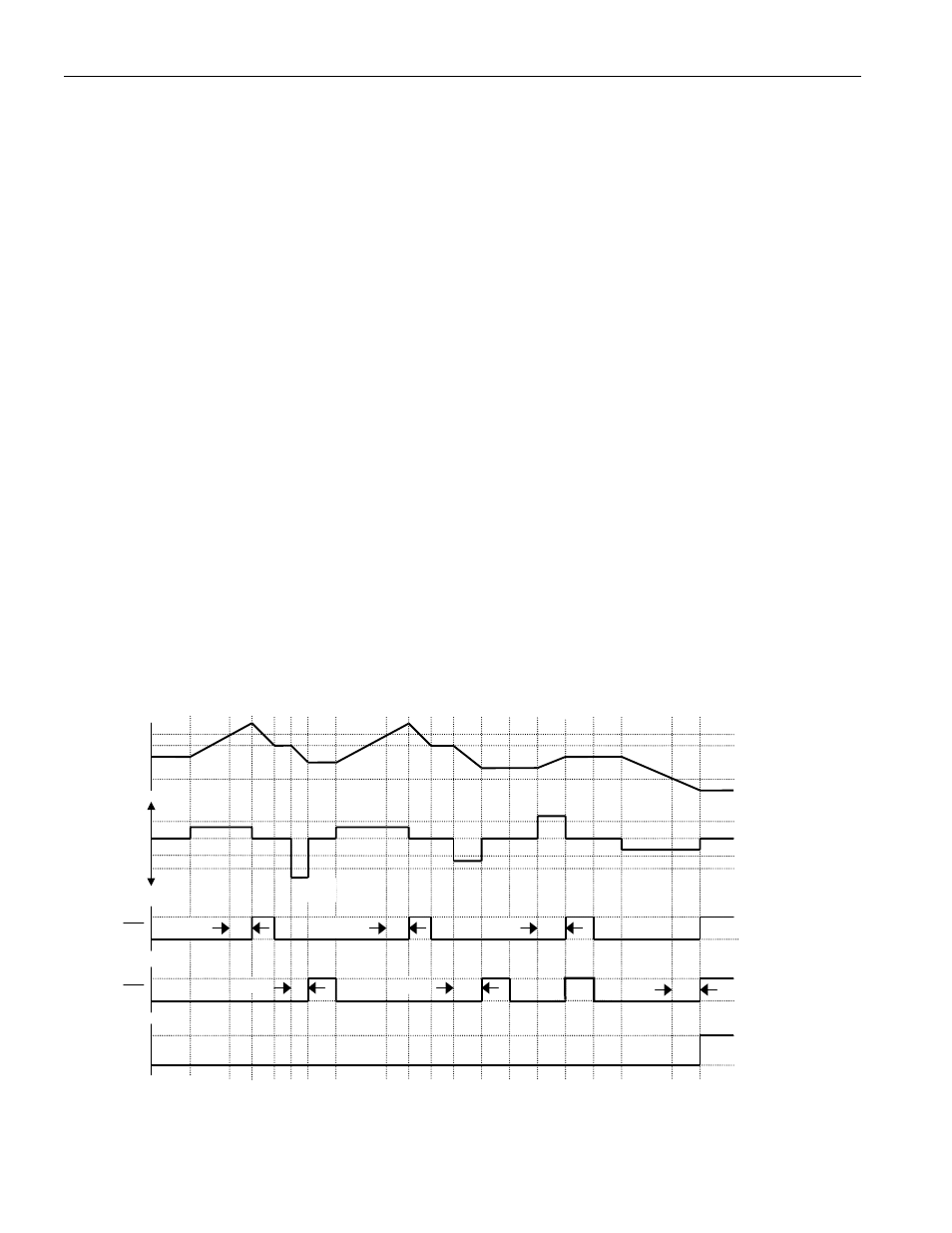
Figure 3. Li+ PROTECTION CIRCUITRY EXAMPLE WAVEFORMS
(1) To allow the device to react quickly to short circuits, detection occurs on the SNS pin rather than on the
filtered IS1 and IS2 pins. The actual short-circuit detect condition is V
SNS
> V
SC
.
SLEEP
MODE
V
OV
V
CE
V
UV
V
CELL
V
IS
CHARGE
DISCHARGE
CC
DC
-V
SC
V
OC
-V
OC
0
t
SCD
t
OCD
t
OCD
t
UVD
t
OVD
V
PLS
V
DD
ACTIVE
V
SS
V
SS
INACTIVE
t
OVD
(1)