Special feature register, Figure 12. special feature register format, Wire bus system – Rainbow Electronics DS2761 User Manual
Page 14: Bit net address, Figure 13. 1-wire net address format, Crc generation
DS2761
14 of 24
SPECIAL FEATURE REGISTER
The format of the special feature register is shown in Figure 12. The function of each bit is described in
detail in the following paragraphs.
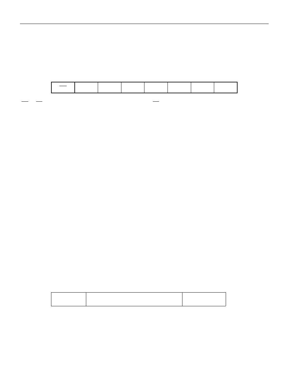
Figure 12. SPECIAL FEATURE REGISTER FORMAT
Address 08
Bit 7
Bit 6
Bit 5
Bit 4
Bit 3
Bit 2
Bit 1
Bit 0
PS
PIO
MSTR
X
X
X
X
X
PS — PS Pin Latch. This bit latches a low state on the PS pin, and is cleared only by writing a 1 to this
location. Writing this bit to a 1 immediately upon reading of a 0 value is recommended.
PIO—PIO Pin Sense and Control. See the Programmable I/O section for details on this read/write bit.
MSTR—SWAP Master Status Bit. This bit indicates whether a device has been selected through the
SWAP command. Selection of this device through the SWAP command and the appropriate net address
results in setting this bit, indicating that this device is the master. A 0 signifies that this device is not the
master.
X—Reserved Bits.
1-WIRE BUS SYSTEM
The 1-Wire bus is a system that has a single bus master and one or more slaves. A multidrop bus is a 1-
Wire bus with multiple slaves. A single-drop bus has only one slave device. In all instances, the DS2761
is a slave device. The bus master is typically a microprocessor in the host system. The discussion of this
bus system consists of four topics: 64-bit net address, hardware configuration, transaction sequence, and
1-Wire signaling.
64-BIT NET ADDRESS
Each DS2761 has a unique, factory-programmed 1-Wire net address that is 64 bits in length. The first
eight bits are the 1-Wire family code (30h for DS2761). The next 48 bits are a unique serial number. The
last eight bits are a cyclic redundancy check (CRC) of the first 56 bits (see Figure 13). The 64-bit net
address and the 1-Wire I/O circuitry built into the device enable the DS2761 to communicate through the
1-Wire protocol detailed in the 1-Wire Bus System section of this data sheet.
Figure 13. 1-WIRE NET ADDRESS FORMAT
8-BIT CRC
48-BIT SERIAL NUMBER
8-BIT FAMILY
CODE (30H)
MSb
LSb
CRC GENERATION
The DS2761 has an 8-bit CRC stored in the most significant byte of its 1-Wire net address. To ensure
error-free transmission of the address, the host system can compute a CRC value from the first 56 bits of
the address and compare it to the CRC from the DS2761. The host system is responsible for verifying the
CRC value and taking action as a result. The DS2761 does not compare CRC values and does not prevent