Ds8024 smart card interface, Applications information, Selector guide – Rainbow Electronics DS8024 User Manual
Page 14: Package information
DS8024
Smart Card Interface
14
______________________________________________________________________________________
Applications Information
Performance can be affected by the layout of the appli-
cation. For example, an additional cross-capacitance of
1pF between card reader contacts C2 (RST) and C3
(CLK) or C2 (RST) and C7 (I/O) can cause contact C2
to be polluted with high-frequency noise from C3 (or
C7). In this case, include a 100pF capacitor between
contacts C2 and CGND.
Application recommendations include the following:
• Ensure there is ample ground area around the
DS8024 and the connector; place the DS8024
very near to the connector; decouple the V
DD
and
V
DDA
lines separately. These lines are best posi-
tioned under the connector.
• The DS8024 and the host microcontroller must use
the same V
DD
supply. Pins CLKDIV1, CLKDIV2,
RSTIN, PRES, AUX1IN, I/OIN, AUX2IN, 5V/3V,
CMDVCC, and OFF are referenced to V
DD
; if pin
XTAL1 is to be driven by an external clock, also
reference this pin to V
DD
.
• Trace C3 (CLK) should be placed as far as possi-
ble from the other traces.
• The trace connecting CGND to C5 (GND) should
be straight (the two capacitors on C1 (VCC)
should be connected to this ground trace).
• Avoid ground loops among CGND, PGND, and GND.
• Decouple V
DDA
and V
DD
separately; if the two
supplies are the same in the application, they
should be connected in a star on the main trace.
• Connect a 100nF capacitor (ESR < 100m
Ω)
between V
CC
and CGND and place near the
DS8024’s V
CC
pin.
• Connect a 100nF or 220nF capacitor (220nF pre-
ferred, ESR < 100m
Ω) between V
CC
and CGND
and place near the smart card socket’s C1 con-
tact.
With all these layout precautions, noise should be kept
to an acceptable level and jitter on C3 (CLK) should be
less than 100ps.
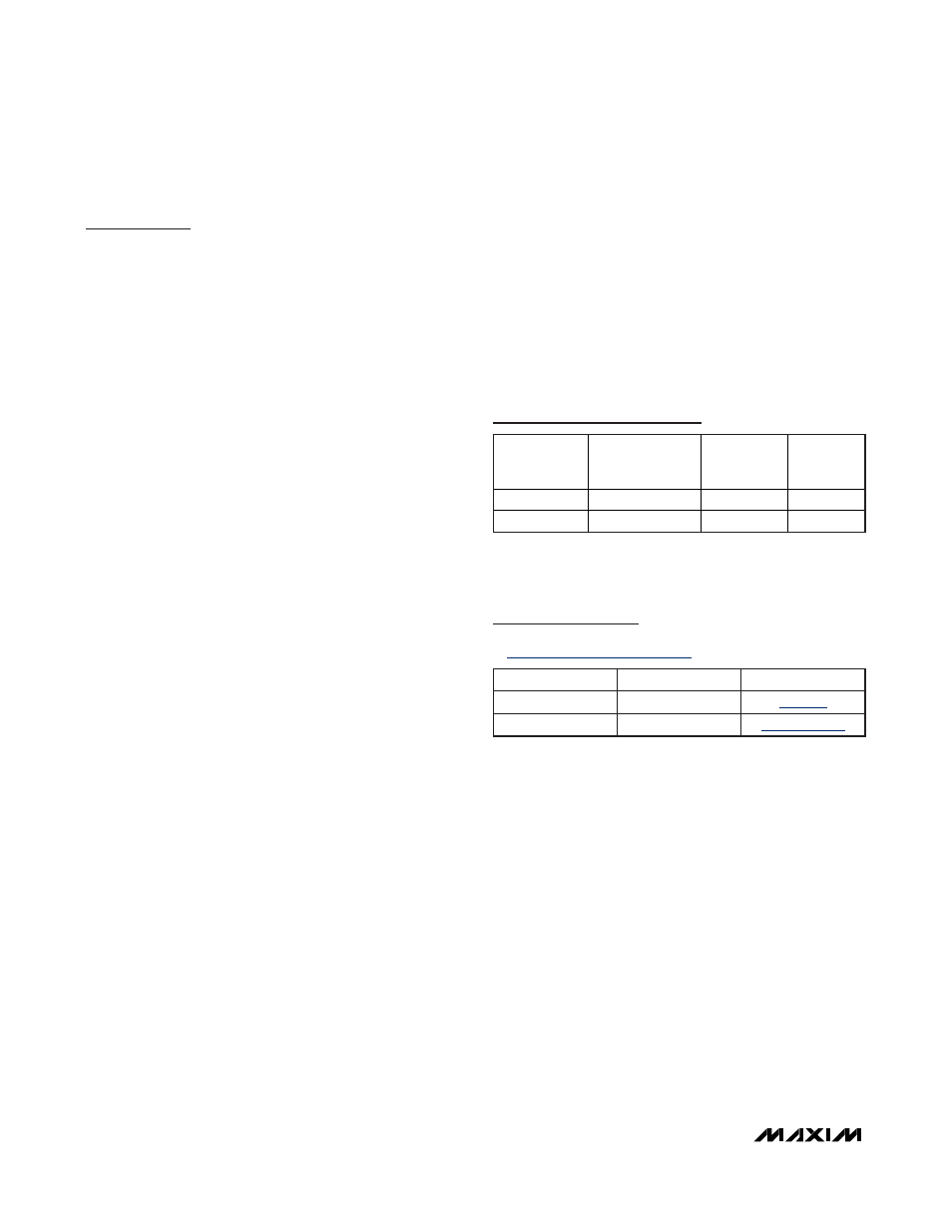
Selector Guide
Note: Contact the factory for availability of other variants and
package options.
+
Denotes a lead-free/RoHS-compliant package.
PART
CURRENT
VOLTAGES
SUPPORTED (V)
SUPPORTS
STOP MODE
PIN-
PACKAGE
DS8024-RJX+
3.0, 5.0
No
28 TSSOP
DS8024-RRX+ 3.0,
5.0
No 28
SO
PACKAGE TYPE
PACKAGE CODE
DOCUMENT NO.
28 SO (300 mils)
—
28 TSSOP
—
Package Information
For the latest package outline information and land patterns, go
to
www.maxim-ic.com/packages
.