Table 3. alarm mask bits – Rainbow Electronics DS1558Y User Manual
Page 9
DS1558
9 of 18
Table 3. ALARM MASK BITS
AM4
AM3
AM2
AM1
ALARM RATE
1
1
1
1
Once per second
1
1
1
0
When seconds match
1
1
0
0
When minutes and seconds match
1
0
0
0
When hours, minutes, and seconds match
0
0
0
0
When date, hours, minutes, and seconds match
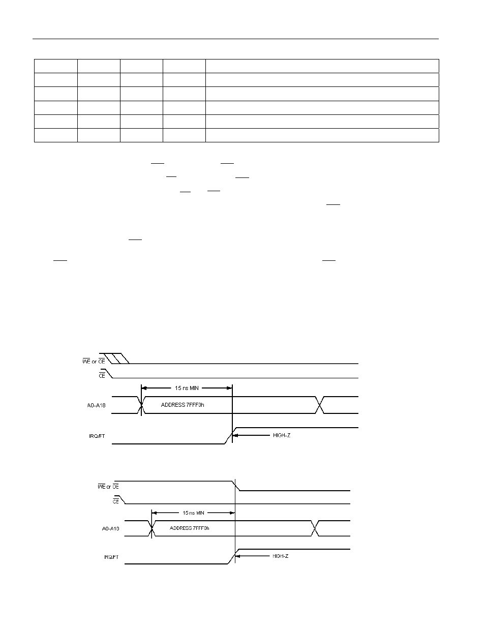
When the RTC register values match alarm register settings, AF is set to a 1. If AE is also set to a 1, the
alarm condition activates the
IRQ
/FT pin. The
IRQ
/FT signal is cleared by a read or write to the flags
register (address 7FFF0h). When
CE
is active, the
IRQ
/FT signal can be cleared by having the address
stable for as short as 15ns and either
OE
or
WE
active, but is not guaranteed to be cleared unless t
RC
is
fulfilled (Figure 2). Once the address has been selected for at least 15ns, the
IRQ
/FT signal can be cleared
immediately, but is not guaranteed to be cleared until t
RC
is fulfilled (Figure 3). The alarm flag is also
cleared by a read or write to the flags register, but the flag does not change states until the end of the
read/write cycle and the
IRQ
/FT signal has been cleared.
The
IRQ
/FT pin can also be activated in the battery-backed mode. The
IRQ
/FT goes low if an alarm
occurs and both ABE and AE are set. The ABE and AE bits are cleared during the power-up transition,
but an alarm generated during power-up sets AF. Therefore, the AF bit can be read after system power-up
to determine if an alarm was generated during the power-up sequence. Figure 4 illustrates alarm timing
during the backup-battery mode and power-up states.
Figure 2. CLEARING IRQ WAVEFORMS ACTIVE
Figure 3. CLEARING IRQ WAVEFORMS