Figure 1. block diagram, Signal descriptions – Rainbow Electronics DS1558Y User Manual
Page 3
DS1558
3 of 18
programmed limits. The DS1558 power-on reset can be used to detect a system power-down or failure
and hold the CPU in a safe reset state until normal power returns and stabilizes; the
RST
output is used
for this function.
The DS1558 also contains its own power-fail circuitry, which automatically protects the data in the clock
and SRAM against out-of-tolerance V
CCI
conditions by inhibiting the
CE
input when the V
CC
supply
enters an out-of-tolerance condition. When V
CCI
goes below the level of V
BAT
, the external battery is
switched on to supply energy to the clock and the external SRAM. This feature provides a high degree of
data security during unpredictable system operation brought on by low V
CC
levels.
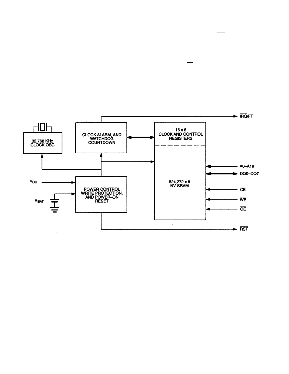
Figure 1. BLOCK DIAGRAM
Note: Any unused upper address pins must be connected to V
CC
to properly address the RTC.
SIGNAL DESCRIPTIONS
A0–A18 – Address inputs for address decode. The DS1558 uses the address inputs to determine whether
or not a read or write cycle should be directed to the attached SRAM or to the RTC registers.
DQ0–DQ7 – Data input/output pins for the RTC registers.
IRQ
/FT – This pin is used to output the alarm interrupt or the frequency test signal. It is open drain and
requires an external pullup resistor.