Oscillator startup time, Clock operations, Clock oscillator control – Rainbow Electronics DS1558Y User Manual
Page 7
DS1558
7 of 18
CLOCK OPERATIONS
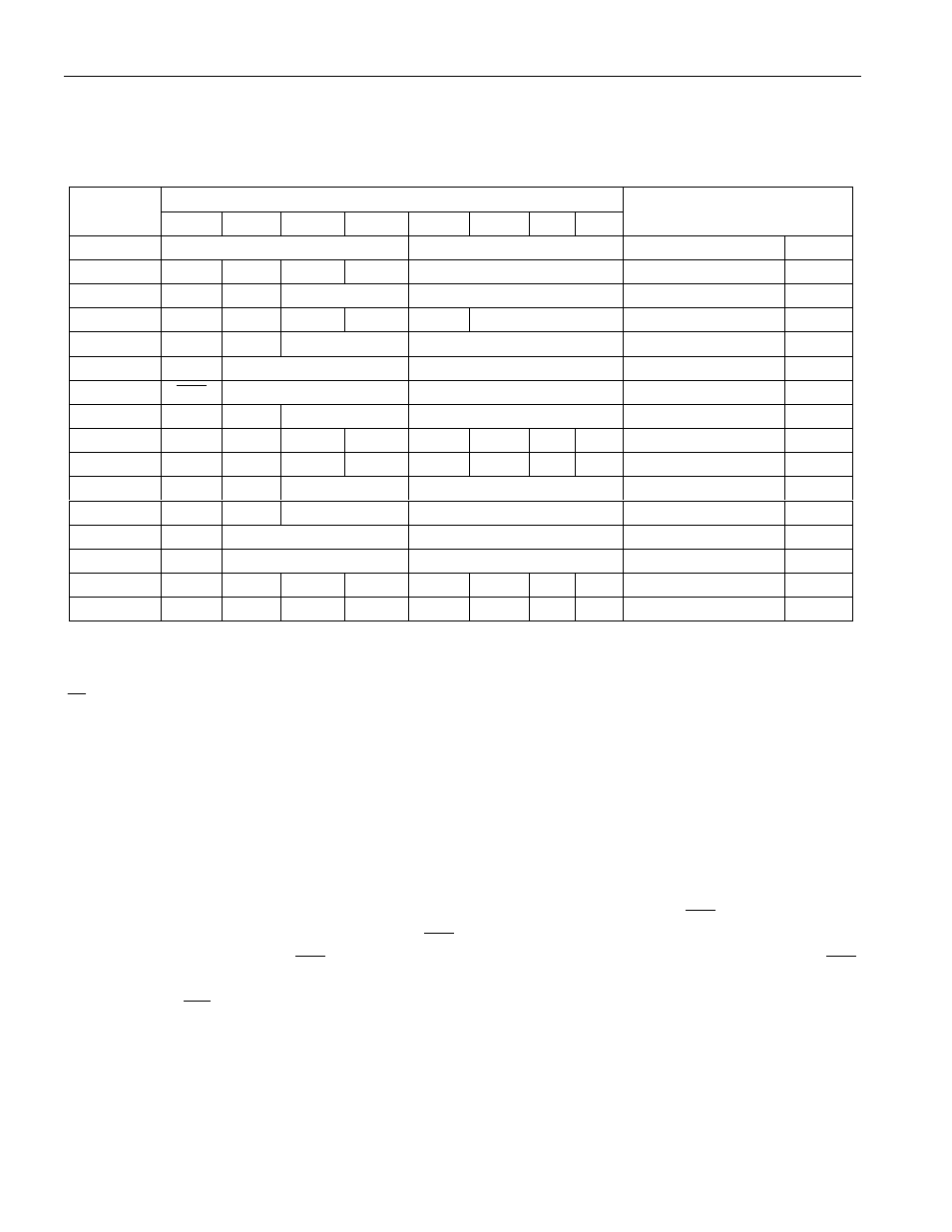
Table 2 and the following paragraphs describe the operation of the RTC, alarm, and watchdog functions.
Table 2. DS1558 REGISTER MAP
DATA
ADDRESS
B
7
B
6
B
5
B
4
B
3
B
2
B
1
B
0
FUNCTION/RANGE
7FFFFh
10 YEAR
YEAR
YEAR
00–99
7FFFEh
X
X
X
10 M
MONTH
MONTH
01–12
7FFFDh
X
X
10 DATE
DATE
DATE
01–31
7FFFCh
X
FT
X
X
X
DAY
DAY
01–07
7FFFBh
X
X
10 HOUR
HOUR
HOUR
00–23
7FFFAh
X
10 MINUTES
MINUTES
MINUTES
00–59
7FFF9h
OSC
10 SECONDS
SECONDS
SECONDS
00–59
7FFF8h
W
R
10 CENTURY
CENTURY
CONTROL
00–39
7FFF7h
WDS
BMB4
BMB3
BMB2
BMB1
BMB0
RB1
RB0
WATCHDOG
—
7FFF6h
AE
Y
ABE
Y
Y
Y
Y
Y
INTERRUPTS
—
7FFF5h
AM4
Y
10 DATE
DATE
ALARM DATE
01–31
7FFF4h
AM3
Y
10 HOURS
HOURS
ALARM HOURS
00–23
7FFF3h
AM2
10 MINUTES
MINUTES
ALARM MINUTES
00–59
7FFF2h
AM1
10 SECONDS
SECONDS
ALARM SECONDS
00–59
7FFF1h
Y
Y
Y
Y
Y
Y
Y
Y
UNUSED
—
7FFF0h
WF
AF
0
BLF
0
0
0
0
FLAGS
—
X = Unused, Read/Writeable Under Write and Read Bit Control
AE = Alarm Flag Enable
FT = Frequency Test Bit
Y = Unused, Read/Writeable Without Write and Read Bit Control
OSC = Oscillator Start/Stop Bit
ABE = Alarm in Backup-Battery Mode Enable
W = Write Bit
AM1–AM4 = Alarm Mask Bits
R = Read Bit
WF = Watchdog Flag
WEN = Watchdog Enable Bit
AF = Alarm Flag
BMB0–BMB4 = Watchdog Multiplier Bits
0 = Reads as a 0 and Cannot Be Changed
RB0–RB1 = Watchdog Resolution Bits
BLF = Battery Low Flag
CLOCK OSCILLATOR CONTROL
The oscillator can be turned off to minimize current drain from the battery. The
OSC
bit is the MSB of
the seconds register (B7 of 7FFF9h). Setting
OSC
to a 1 stops the oscillator; setting to a 0 starts the
oscillator. The initial state of
OSC
is not guaranteed. When power is applied for the first time, the
OSC
bit should be enabled. Oscillator operation and frequency can be verified by setting the FT bit and
monitoring the
IRQ
/FT pin for 512Hz.
OSCILLATOR STARTUP TIME
Oscillator startup times are highly dependent upon crystal characteristics and layout. High ESR and
excessive capacitive loads are the major contributors to long startup times. A circuit using a crystal with
the recommended characteristics and following the recommended layout usually starts within 1 second.