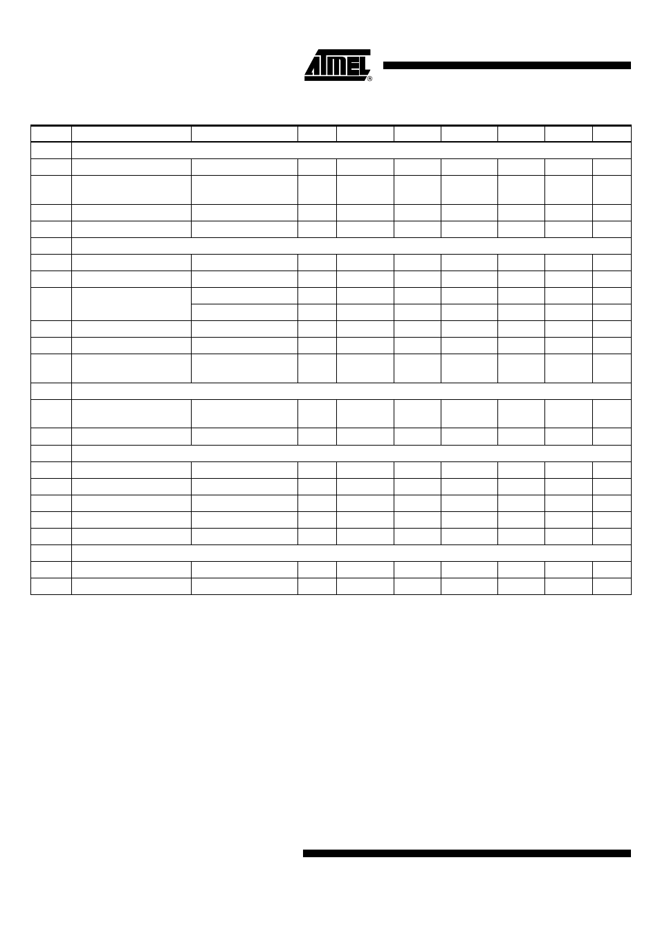
Atr0601 [preliminary, Electrical characteristics (continued) – Rainbow Electronics ATR0601 User Manual
Page 6
6
4866A–GPS–08/05
ATR0601 [Preliminary]
2
Mixer
2.1
Output frequency
f
XTO
= 23.104 MHz
13, 14
f
IF
96.764
MHz
A
2.2
Input impedance
(balanced)
f
RF
= 1575.42 MHz
10, 11
Z
11
10-j80
Ω
C
2.3
Conversion Gain
Recommended IF-filter
8
G
MIX
20
dB
B
2.4
Noise figure (SSB)
8
NF
MIX
5.8
dB
C
3
VGA/AGC
3.1
Minimum gain
V
AGCO
= 1.0V
G
VGA,min
0
dB
B
3.2
Maximum gain
V
AGCO
= 2.2V
G
VGA,max
70
dB
B
3.3
Control-voltage sensitivity
V
AGCO
= 2.2V
N
VGA,min
6.6
dB/V
D
V
AGCO
= 1.0V
N
VGA,max
150
dB/V
D
3.4
AGC cut-off frequency
C
ext
= open
2
f
3dB_AGC
250
kHz
D
3.5
AGC cut-off frequency
C
ext
= 100 pF
2
f
3dB_AGC
33
kHz
D
3.6
Gain-control output
voltage
2
V
AGCO
0.9
2.3
V
B
4
Reference Oscillator
4.1
XTO phase noise at
100 Hz
With specified crystal
24
Pn
100
–80
dBc/Hz
C
4.2
XTO phase noise at 1 kHz With specified crystal
24
Pn
1k
–100
dBc/Hz
C
5
Clock and Data Driver
5.1
Clock driver frequency
f
XTO
= 23.104 MHz
24
f
CLK
23.104
MHz
A
5.2
Clock output level
C
load,max
= 10 pF
24
V
CLK,high
0.9
×
V
DIG
V
B
5.3
Clock output level
C
load.max
= 10 pF
24
V
CLK,low
0.1
×
V
DIG
V
B
5.4
Data output level
C
load,max
= 10 pF
22, 23
V
Data,high
0.9
×
V
DIG
V
B
5.5
Data output level
C
load,max
= 10 pF
22, 23
V
Data,low
0.1
×
V
DIG
V
B
6
PMSS
6.1
Voltage level power-on
17, 18
V
PU,on
1.3
V
A
6.2
Voltage level power-off
17, 18
V
PU,off
0.5
V
A
7.
Electrical Characteristics (Continued)
No.
Parameters
Test Conditions
Pin
Symbol
Min.
Typ.
Max.
Unit
Type*
*) Type means: A = 100% tested, B = 100% correlation tested, C = Characterized on samples, D = Design parameter
Notes:
1. Conditions: V
CC
= 2.7V; V
DIG
= 1.65V; Temperature = 27°C
2. Capacitive load (C
L
= 3.3 pF) at pins 22, 23, 24
3. Capacitive load (C
L
= 3.3 pF) at pin 24