Ds3690, 3v 26-channel, three-stateable transmission gate, Detailed description – Rainbow Electronics DS3690 User Manual
Page 6: Applications information, Typical operating circuit
DS3690
Detailed Description
The DS3690 is a 26-channel, noninverting, bidirectional
CMOS transmission gate, and is intended for use in
applications where a downstream component must be
isolated from a common control, address, or data bus in
a timely fashion. Each of the 26 independent channels
can be used for input, output, or I/O signal applications.
The chip-enable input (CE) allows gated bus control for
either signal transmission or bus isolation.
Each independent channel consists of two pins
(“CHxxA” and “CHxxB” where xx is 01–26). Since all 26
channels are capable of bidirectional function, either
CHxxA or CHxxB can be selected as the input pin for
any unidirectional signal requirements. A change of
logic state on one side of any channel is directly reflect-
ed on the other side of that channel. Signal
propagation delay (CHxxA to CHxxB, or CHxxB to
CHxxA) is illustrated in Figure 1 as t
PD
.
All channels can be simultaneously enabled or forced
to a high-impedance state using the CE input. When CE
becomes a logic zero, all channels are enabled for
signal transmission within t
CEV
(see Figure 2). When CE
becomes a logic one, all channels are forced to a
high-impedance state within t
CEZ
(see Figure 3).
Applications Information
Power-Supply Decoupling
To achieve the best results when using the DS3690,
decouple the power supply with a 0.1µF capacitor.
Use a high-quality, ceramic surface-mount capacitor if
possible. Surface-mount components minimize lead
inductance, which improves performance, while ceram-
ic capacitors have adequately high-frequency
response for decoupling applications.
Pin Connections
For optimum circuit operation, connect pins 25 and 53 to
a common ground. The exposed pad on the package
bottom side should be connected to ground.
To prevent an unused transmission channel from gener-
ating any undesired activity, it is recommended that one
side of that unused channel be connected to ground
(either the A or B terminal, at the designer’s discretion).
3.3V 26-Channel, Three-Stateable
Transmission Gate
6
_______________________________________________________________________________________
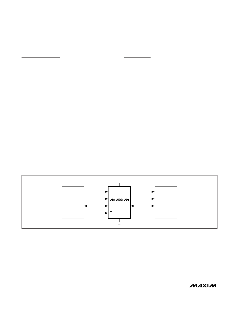
MICRO
EXTERNAL
MEMORY
R/W CONTROL
ADDRESS (A
0–X
)
I/O (DQ
0–X
)
R/W CONTROL
ADDRESS (A
0–X
)
I/O (DQ
0–X
)
+3.3V
CE
BUS ENABLE
DS3690
Typical Operating Circuit