Typical operating circuit – Rainbow Electronics DS1302 User Manual
Page 2
DS1302
2 of 15
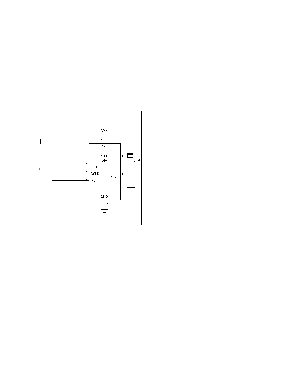
Interfacing the DS1302 with a microprocessor is simplified by using synchronous serial communication.
Only three wires are required to communicate with the clock/RAM: 1)
RST
(reset), 2) I/O (data line), and
3) SCLK (serial clock). Data can be transferred to and from the clock/RAM 1 byte at a time or in a burst
of up to 31 bytes. The DS1302 is designed to operate on very low power and retain data and clock
information on less than 1 microwatt.
The DS1302 is the successor to the DS1202. In addition to the basic timekeeping functions of the
DS1202, the DS1302 has the additional features of dual-power pins for primary and back-up power
supplies, programmable trickle charger for V
CC1
, and seven additional bytes of scratchpad memory.
TYPICAL OPERATING CIRCUIT
- MAX6869 (17 pages)
- TNY-A9260-C01 (5 pages)
- MAX34441 (53 pages)
- MAX4912 (13 pages)
- QIL-A9260-C11 (1 page)
- QIL-A9260-C11 (34 pages)
- QIL-A9260-C11 (20 pages)
- USB-A9263-C02 (1 page)
- DAB-GPS-C01 (15 pages)
- DAB-GPS-C01 (28 pages)
- DAB-CAM-C01 (27 pages)
- DAB-WLS-C01 (WiFi) (20 pages)
- USB-A9G20-C01 (1 page)
- MAX34440 (43 pages)
- SBC35-A9260-C12 (28 pages)
- SBC35-A9260-C12 (1 page)
- MAX16024 (17 pages)
- USB-A9G20-C11 (5 pages)
- DAB-IMU-C01 (20 pages)
- MAX16021 (21 pages)
- DAB-WLS-C11 (BlueTooth) (2 pages)
- SBC35-A9G20-C11 (24 pages)
- MAX16054 (9 pages)
- MAX14525 (7 pages)
- MAX16066 (61 pages)
- USB-A9260-C12 (1 page)
- DS1803 (11 pages)
- DS12887A (2 pages)
- DS1339 (18 pages)
- DS1858 (22 pages)
- DS1267 (12 pages)
- DS12С887A (2 pages)
- DS1804 (7 pages)
- DS1091L (6 pages)
- DS1669S (10 pages)
- DS1867 (14 pages)
- DS1087L (12 pages)
- DS4026 (13 pages)
- DS1286 (13 pages)
- DS1801 (10 pages)
- DS1254 (17 pages)
- DS17887 (38 pages)
- DS1691 (4 pages)
- DS1615 (24 pages)
- DS1868 (14 pages)