Rainbow Electronics DAB-GPS-C01 User Manual
Page 11
LEA-5H, LEA-5S, LEA-5A - Data Sheet
Preliminary
u-blox proprietary
GPS.G5-MS5-07026-P4
Page 11
your position is our focus
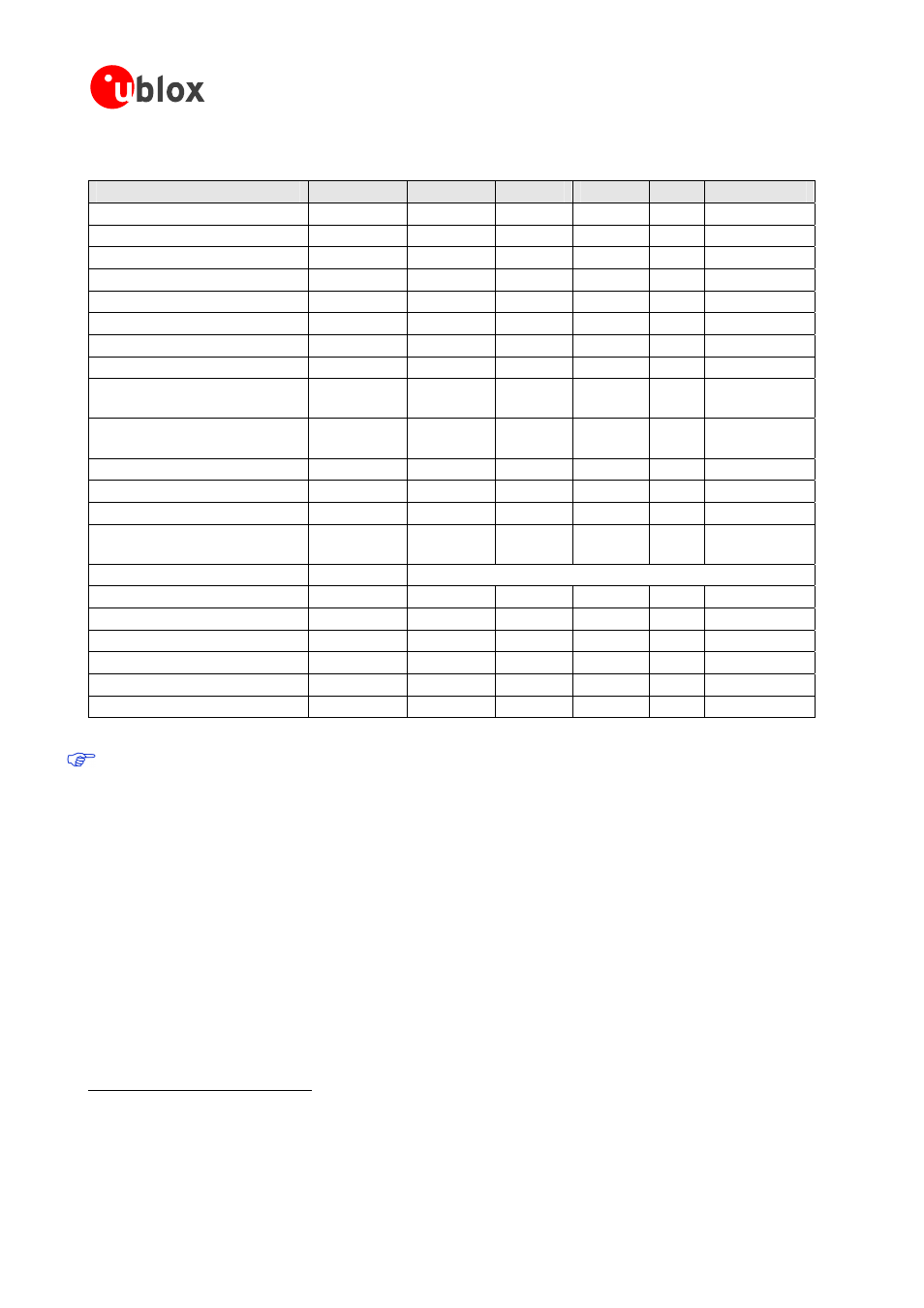
4.2 Operating Conditions
Parameter
Symbol
Min
Typ
Max
Units Condition
Power supply voltage (VCC)
Vcc
2.7
3.6
V
Sustained supply current
Icc
40
mA
Vcc = 3.0 V
Peak supply current
Iccp
150
mA
Vcc = 3.6 V
Backup battery voltage
Vbckp
1.3
4.8
V
Backup battery current
Ibckp
30
μA
Vbckp = 1.8V
Input pin voltage range
Vin
Vcc +0.5 V
Input pin low voltage
Vin_low_1
0.2x Vcc
V
Input pin high voltage
Vin_high_1
0.7x Vcc
V
Input pin low voltage for
EXTINT0 and RxD1
Vin_low_2
0.22
V
Input pin high voltage for
EXTINT0 and RxD1
Vin_high_2
0.91
V
Output pin voltage range
Vout
V
Output pin low voltage
Vout_low
0.4
V
Iout = 4 mA
Output pin high voltage
Vout_high
Vcc – 0.4
V
Iout = -4 mA
VDDUSB (Pin 24) for USB
operation
Vddusb1
3.0
3.6
V
USB_DM, USB_DP
VinU
Compatible with USB with 27 Ohms series resistance
Antenna gain
Gant
30
dB
V_ANT antenna bias voltage
Vant
2.7
5.5
V
I
ANT
< -50 mA
Antenna bias voltage drop
Vant_drop
0.1
Iccrf=50mA
VCC_RF voltage
Vccrf
Vcc-0.1
V
VCC_RF output current
Iccrf
50
mA
Operating temperature
Topr
-40
85
°C
Table 10: Operating Conditions
Operation beyond the "Operating Conditions" is not recommended and extended exposure beyond the
"Operating Conditions" may affect device reliability.
6
All specification are at an ambient temperature of 25°C.
7
Average current drawn during Continuous Tracking Mode with 1 Hz update rate, using 9 channels for tracking and navigation and 3
channels for searching satellites (= acquisition). Use this figure to determine required battery capacity.
8
Peak current drawn during initial acquisition phase. Use this figure to dimension maximum current capability of power supply.
9
If USB not used connect to GND