Motor driver ics ba6287f – Rainbow Electronics BA6287F User Manual
Page 3
441
Motor driver ICs
BA6287F
F
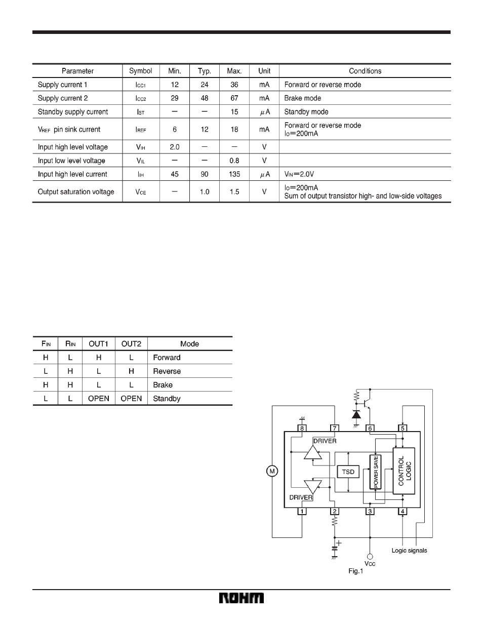
Electrical characteristics (unless otherwise noted, Ta = 25
_
C, V
CC
= 9V, V
M
=9V, V
REF
= 9V)
F
Circuit operation
(1)
Input section
The four output modes are controlled by two logic inputs.
Current flows from OUT1 to OUT2 when F
IN
is HIGH and
R
IN
is LOW, and from OUT2 to OUT1 when R
IN
is HIGH
and F
IN
is LOW (refer to the truth table). The input circuit
can be operated by a logic circuit with a current capacity
of 120
X
170
µ
A.
Input / output truth table
(2)
Output section
Current flows from OUT1 to OUT2 during forward rota-
tion, and from OUT2 to OUT1 during reverse rotation.
The output voltages V
OH
and V
OL
are given by :
V
OH
[V]=V
REF
*
V
CE
(sat)
(PNP)
*
V
BE
(NPN)
V
OL
[V]=V
CE
(sat)
(NPN)
V
CE
and V
BE
are functions of the output current (see elec-
trical characteristic curves). The output current can be
set with the V
REF
pin.
(3)
Power saving circuit
All circuits are turned OFF when the F
IN
and R
IN
input pins
are both put to LOW level. This circuit saves power dur-
ing standby mode by leaving the outputs OPEN.
(4)
Thermal shutdown circuit
When the thermal shutdown circuit is activated at the
chip temperature of about 175
_
C (typical), the outputs
are left OPEN. The temperature difference between the
activation and deactivation settings is about 15
_
C. When
the thermal shutdown circuit is deactivated, the outputs
revert to the status determined by input mode.
F
Application example