Atr1842 [preliminary, Absolute maximum ratings, Recommended operating conditions – Rainbow Electronics ATR1842 User Manual
Page 4: Electrical characteristics: general
4
9109AS–DVD–08/07
ATR1842 [Preliminary]
3.
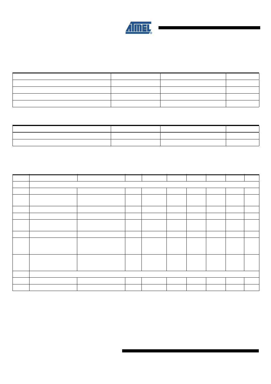
Absolute Maximum Ratings
Stresses beyond those listed under “Absolute Maximum Ratings” may cause permanent damage to the device. This is a stress rating
only and functional operation of the device at these or any other conditions beyond those indicated in the operational sections of this
specification is not implied. Exposure to absolute maximum rating conditions for extended periods may affect device reliability.
Parameters
Symbol
Value
Unit
Supply voltage
V
CC
–0.5 to +6.0
V
Input voltage at any input
V
in
–0.5 to VCC – 0.5
V
Storage temperature
T
stg
–40 to +100
°C
Soldering temperature QFN_Open package
T
sol
260
°C
4.
Recommended Operating Conditions
Parameters
Symbol
Value
Unit
Supply voltage
V
CC
4.5 to 5.5
V
Operating temperature range
T
amb
–10 to +80
°C
5.
Electrical Characteristics: General
V
CC
= 5V, T
amb
= 25°C,
λ
= 405 nm/780 nm/650 nm
Output load: R
load
= 10 k
Ω
, C
load
= 20 pF
No.
Parameters
Test Conditions
Pin
Symbol
Min.
Typ.
Max.
Unit
Type*
1
DC Specifications, Power Supply
1.1
Supply current
I
CC
28
30
mA
A
1.2
Supply current
(standby mode)
I
CC
0.5
mA
A
1.3
V
REF_INT
1.65
V
A
1.4
TCV
REF_INT
15
µV/°C
C
1.5
Maximum output voltage
V
out
VCC –
0.9
V
C
1.6
Minimum output voltage
V
out
0.3
V
C
1.7
Power supply rejection
ratio
Low-frequency (10 kHz),
inclusive application/
flexboard
PSRR
–45
dB
C
1.8
Power supply rejection
ratio
High-frequency
(100 kHz), inclusive
application/ flexboard
PSRR
–45
dB
C
2
Output Offset Voltage
2.1
Output offset
V
REF
– V
RF+
, V
REF
– V
RF–
V
OFF1
–20
0
+20
mV
C
2.2
Offset drift
dV
OFF
/dT
–25
+25
µV/°C
C
*) Type means: A = 100% tested, B = 100% correlation tested, C = Characterized on samples, D = Design parameter