Security fuse usage, Programming/erasing, Input and i/o pull-ups – Rainbow Electronics ATF20V8CQZ User Manual
Page 3: Input diagram, I/o diagram, Atf20v8c family, Input diagram i/o diagram
3
ATF20V8C Family
0408H–04/01
Security Fuse Usage
A single fuse is provided to prevent unauthorized copying
of the ATF20V8C’s fuse patterns. Once programmed, fuse
verify and preload are inhibited. However, the 64-bit User
Signature remains accessible.
The security fuse should be programmed last, as its effect
is immediate.
Programming/Erasing
Programming/erasing is performed using standard PLD
programmers. For further information, see the Configurable
Logic data book section titled, “CMOS PLD Programming
Hardware and Software Support.”
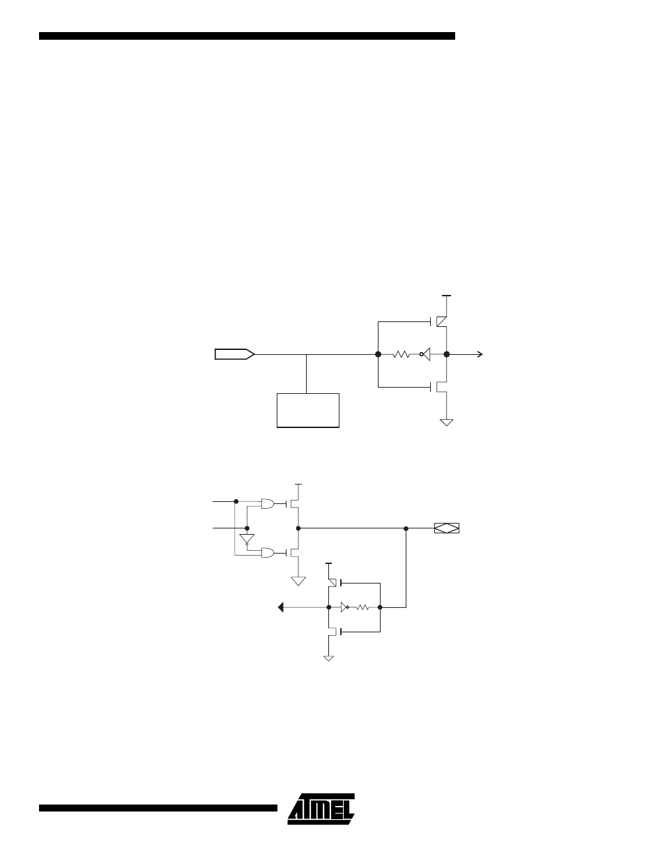
Input and I/O Pull-ups
All ATF20V8C family members have internal input and I/O
“pin-keeper” circuits. Therefore, whenever inputs or I/Os
are not being driven externally, they will maintain their last
driven state. This ensures that all logic array inputs and
device outputs are at known states. These are relatively
weak active circuits that can be easily overridden by TTL-
compatible drivers (see input and I/O diagrams below).
Input Diagram
I/O Diagram
100K
V
CC
ESD
PROTECTION
CIRCUIT
INPUT
100K
VCC
VCC
DATA
OE
I/O
INPUT