Crc generation, Hardware configuration – Rainbow Electronics DS2784 User Manual
Page 31
DS2784: 1-Cell Stand-Alone Fuel Gauge IC with Li+ Protector and SHA-1 Authentication
CRC GENERATION
The DS2784 has an 8-bit CRC stored in the most significant byte of its 1-Wire net address and generates a CRC
during some command protocols. To ensure error-free transmission of the address, the host system can compute a
CRC value from the first 56 bits of the address and compare it to the CRC from the DS2784.
The host system is responsible for verifying the CRC value and taking action as a result. The DS2784 does not
compare CRC values and does not prevent a command sequence from proceeding as a result of a CRC mismatch.
Proper use of the CRC can result in a communication channel with a very high level of integrity.
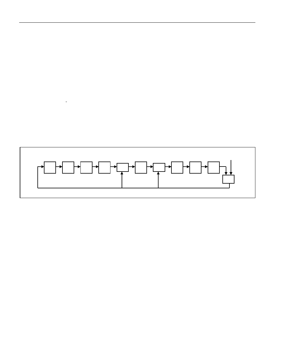
The CRC can be generated by the host using a circuit consisting of a shift register and XOR gates as shown in
Figure 7, or it can be generated in software using the polynomial X
8
+ X
5
+ X
4
+ 1. Additional information about the
Dallas 1-Wire CRC is available in Application Note 27: Understanding and Using Cyclic Redundancy Checks with
Dallas Semiconductor iButton Products
.
In the circuit in Figure 7, the shift register bits are initialized to 0. Then, starting with the least significant bit of the
family code, one bit at a time is shifted in. After the 8th bit of the family code has been entered, then the serial
number is entered. After the 48th bit of the serial number has been entered, the shift register contains the CRC
value.
Figure 7. 1-Wire CRC Generation Block Diagram
MSb
XOR
XOR
LSb
XOR
INPUT
During some command sequences, the DS2784 also generates an 8-bit CRC and provides this value to the bus
master to facilitate validation for the transfer of command, address, and data from the bus master to the DS2784.
The DS2784 computes an 8-bit CRC for the command and address bytes received from the bus master for the
read memory, read status, and read/generate CRC commands to confirm that these bytes have been received
correctly. The CRC generator on the DS2784 is also used to provide verification of error-free data transfer as each
EEPROM page is sent to the master during a Read Data/Generate CRC command and for the 8 bytes of
information in the status memory field.
In each case where a CRC is used for data transfer validation, the bus master must calculate the CRC value using
the same polynomial function and compare the calculated value to the CRC either stored in the DS2784 Net
Address or computed by the DS2784. The comparison of CRC values and decision to continue with an operation
are determined entirely by the bus master. There is no circuitry in the DS2784 that prevents the command
sequence from proceeding if the stored or calculated CRC from the DS2784 and the calculated CRC from the host
do not match.
HARDWARE CONFIGURATION
Because the 1-Wire bus has only a single line, it is important that each device on the bus be able to drive it at the
appropriate time. To facilitate this, each device attached to the 1-Wire bus must connect to the bus with open-drain
or tri-state output drivers. The DS2784 uses an open-drain output driver as part of the bidirectional interface
circuitry shown in Figure 8. If a bidirectional pin is not available on the bus master, separate output, and input pins
can be connected together.
31 of 38