Rainbow Electronics DS2784 User Manual
Page 26
DS2784: 1-Cell Stand-Alone Fuel Gauge IC with Li+ Protector and SHA-1 Authentication
BL1
—Parameter EEPROM Block 1 Lock Flag. A 1 in this read-only bit indicates that EEPROM block 1 (addresses
60h to 7Fh) is locked (read only) while a 0 indicates block 1 is unlocked (read/write).
BL0
—User EEPROM Block 0 Lock Flag. A 1 in this read-only bit indicates that EEPROM block 0 (addresses 20h to
2Fh is locked (read only) while a 0 indicates block 0 is unlocked (read/write).
X
– Reserved Bits.
MEMORY
The DS2784 has a 256-byte linear memory space with registers for instrumentation, status, and control, as well as
EEPROM memory blocks to store parameters and user information. Byte addresses designated as “Reserved”
typically return FFh when read. These bytes should not be written. Several byte registers are paired into two-byte
registers in order to store 16-bit values. The most significant byte (MSB) of the 16-bit value is located at the even
address and the least significant byte (LSB) is located at the next address (odd) byte. When the MSB of a two-byte
register is read, the MSB and LSB are latched simultaneously and held for the duration of the Read Data
command. This prevents updates to the LSB during the read ensuring synchronization between the two register
bytes. For consistent results, always read the MSB and the LSB of a two-byte register during the same read data
sequence.
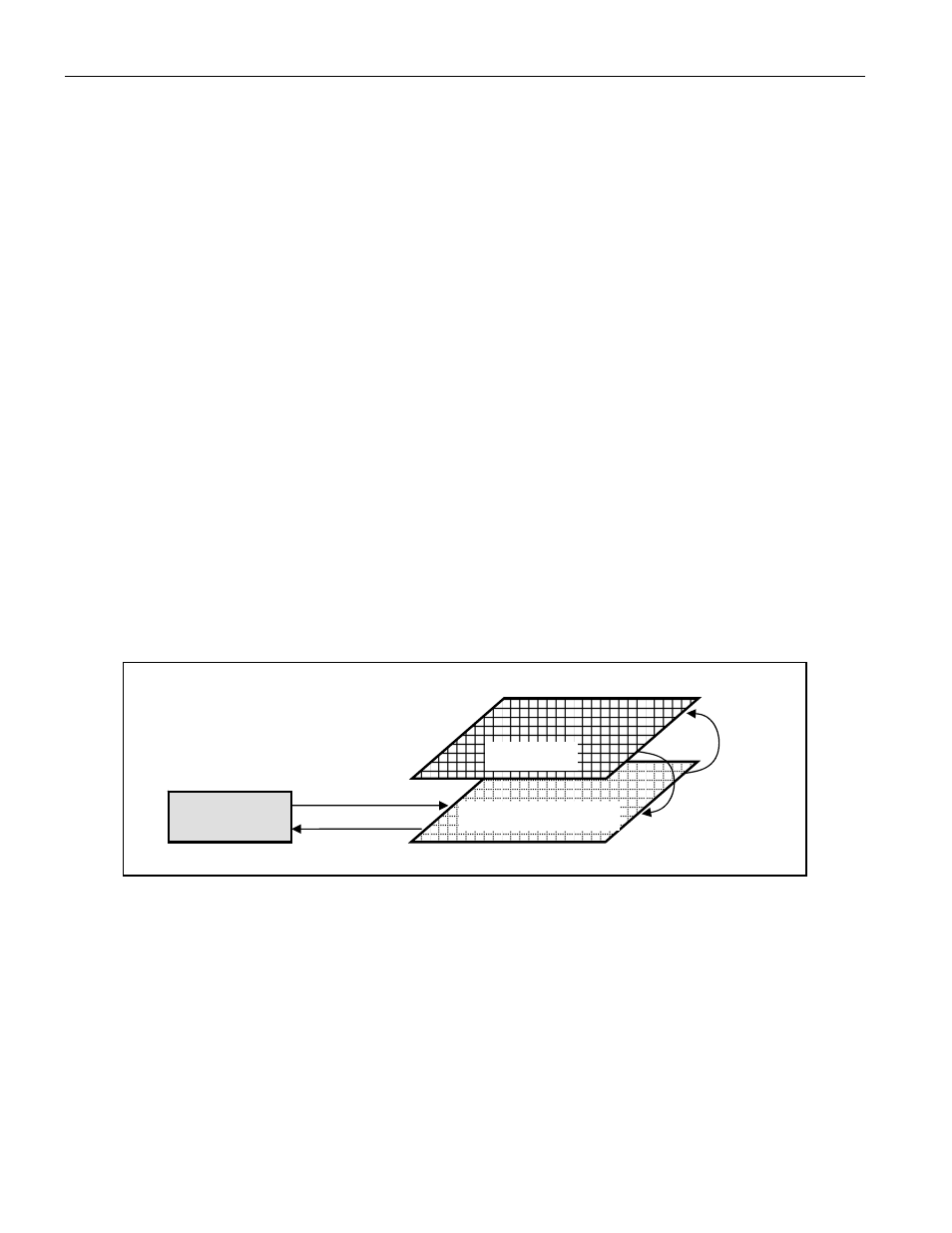
EEPROM memory consists of nonvolatile (NV) EEPROM cells overlaying volatile shadow RAM. The read data and
write data protocols allow the 1-Wire interface to directly accesses the shadow RAM only. The Copy Data and
Recall Data Function commands transfer data between the EEPROM cells and the shadow RAM. In order to
modify the data stored in the EEPROM cells, data must be written to the shadow RAM and then copied to the
EERPOM. To verify the data stored in the EEPROM cells, the EEPROM data must be recalled to the shadow RAM
and then read from the shadow. After issuing the Copy Data Function command, access to the EEPROM block is
not available until the EEPROM copy completes, which takes 2ms typically (see t
EEC
in the Electrical Characteristics
table).
Figure 5. EEPROM Access via Shadow RAM
SERIAL
INTERFACE
WRITE
READ
SHADOW RAM
EEPROM
COPY
RECALL
USER EEPROM—BLOCK 0
A 16-byte user EEPROM memory (block 0, addresses 20h–2Fh) provides NV memory that is uncommitted to other
DS2784 functions. Accessing the user EEPROM block does not affect the operation of the DS2784. User EEPROM
is lockable; once locked, write access is not allowed. The battery pack or host system manufacturer can program
lot codes, date codes, and other manufacturing or warranty or diagnostic information and then lock it to safeguard
the data. User EEPROM can also store parameters for charging to support different size batteries in a host device
as well as auxiliary model data such as time to full charge estimation parameters.
PARAMETER EEPROM—BLOCK 1
Model data for the cells, as well as application operating parameters, are stored in the parameter EEPROM (block
1, addresses 60h–7Fh). The ACR (MSB and LSB) and AS registers are automatically saved to EEPROM when the
RARC result crosses 4% boundaries. This allows the DS2784 to be located outside the protection FETs.
26 of 38