Rainbow Electronics DS2784 User Manual
Page 10
DS2784: 1-Cell Stand-Alone Fuel Gauge IC with Li+ Protector and SHA-1 Authentication
DS2784 shuts off both external FETs and sets the COC flag in the protection register. The charge current path is
not re-established until the voltage on the PLS pin drops below V
DD
- V
TP
. The DS2784 provides a pulldown current
(I
TST
) from PLS to V
SS
to pull PLS down in order to detect the removal of the offending charge current source.
Overcurrent, Discharge Direction (DOC).
Discharge current develops a positive voltage on V
SNS
with respect to
V
SS
. If V
SNS
exceeds the discharge overcurrent threshold (V
DOC
) for a period longer than t
OCD
, the DS2784 shuts off
the external discharge FET and sets the DOC flag in the protection register. The discharge current path is not re-
established until the voltage on PLS rises above V
DD
- V
TP
. The DS2784 provides a test current (I
TST
) from V
DD
to
PLS to pull PLS up in order to detect the removal of the offending low-impedance load.
Short Circuit.
If V
SNS
exceeds short-circuit threshold V
SC
for a period longer than short-circuit delay (t
SCD
), the
DS2784 shuts off the external discharge FET and sets the DOC flag in the protection register. The discharge
current path is not re-established until the voltage on PLS rises above V
DD
- V
TP
. The DS2784 provides a test
current of value (I
TST
) from V
DD
to PLS to pull PLS up in order to detect the removal of the short circuit.
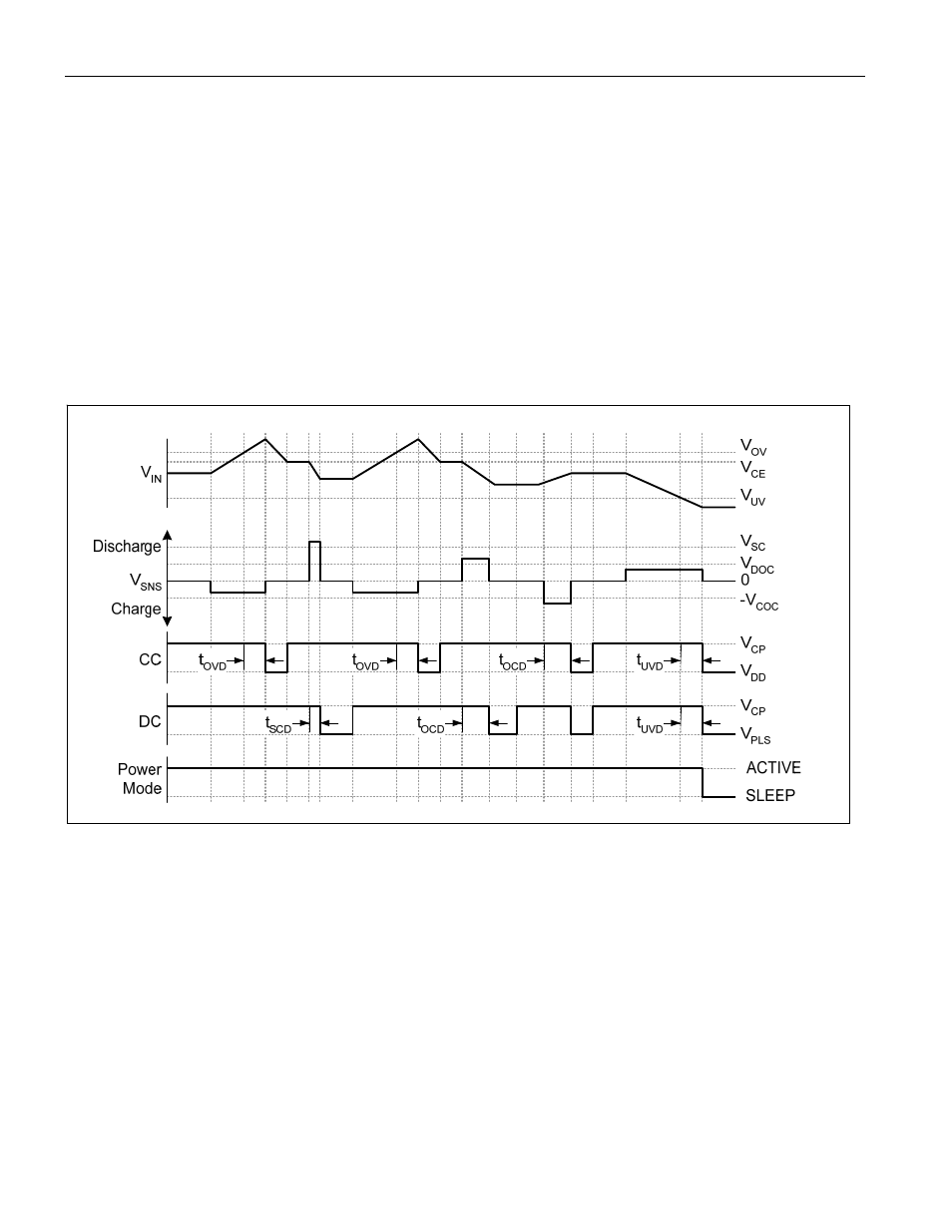
Figure 2. Li+ Protection Circuitry Example Waveforms
Summary.
All the protection conditions previously described are logic ANDed to affect the CC and DC outputs.
CC = (
Overvoltage) AND (Undervoltage) AND (Overcurrent, Charge Direction)
AND (Protection Register Bit CE)
DC = (
Undervoltage) AND (Overcurrent, Either Direction) AND (Short Circuit)
AND (Protection Register Bit DE
)
PROTECTION REGISTER FORMAT
The protection register reports events detected by the Li+ safety circuit on bits 2 to 7. Bits 0 and 1 are used to
disable the charge and discharge FET gate drivers. Bits 2 to 7 are set by internal hardware only. Bits 2 and 3 are
cleared by hardware only. Bits 4 to 7 are cleared by writing the register with a 0 in the bit position of interest. Writing
10 of 38