Electrical characteristics: 1-wire interface – Rainbow Electronics DS2770 User Manual
Page 27
DS2770
27 of 27
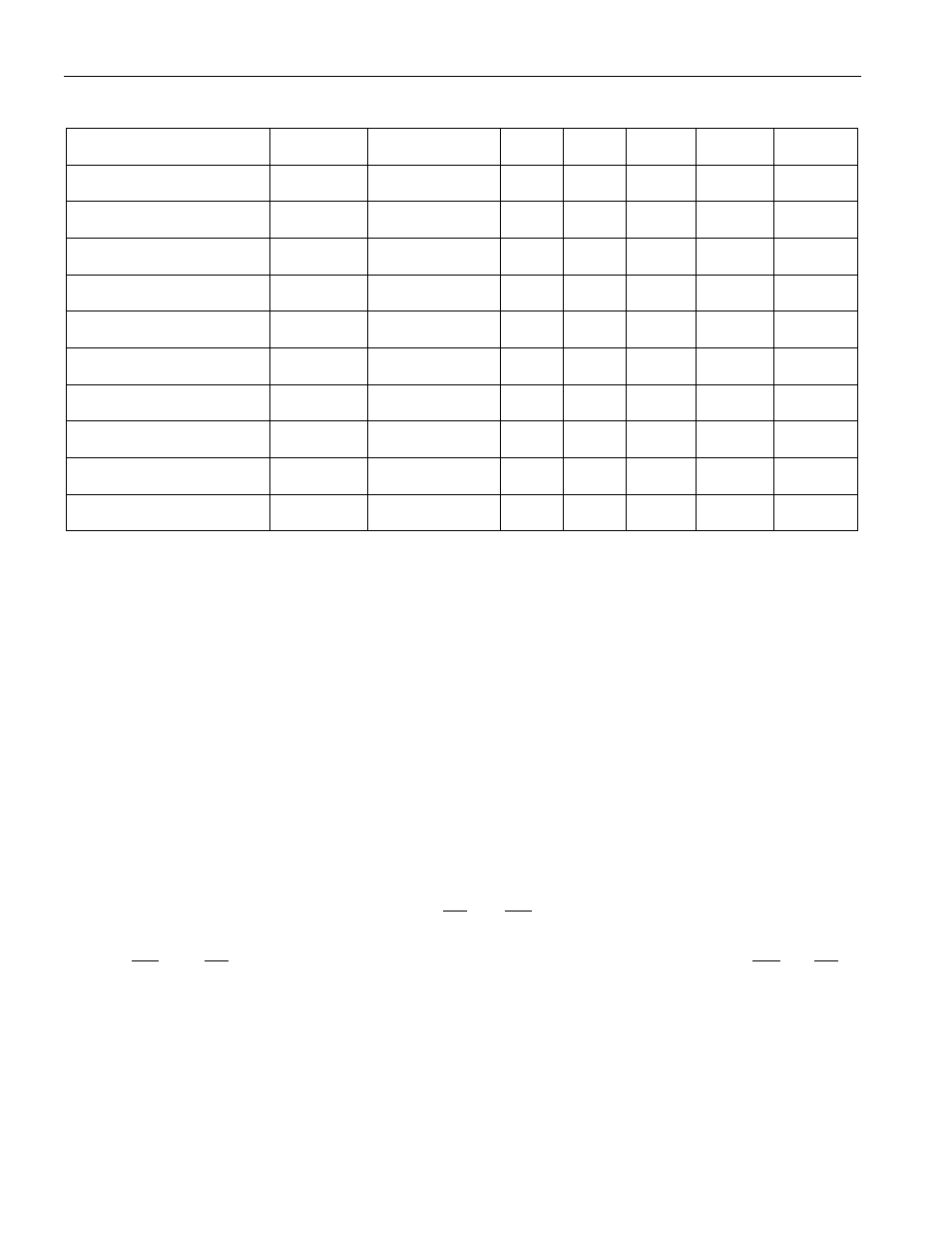
ELECTRICAL CHARACTERISTICS:
1-WIRE INTERFACE
(-20
°C to 70°C, 2.7V £ V
DD
£ 5.5V)
PARAMETER
SYMBOL CONDITION
MIN
TYP
MAX
UNITS NOTES
Time Slot
t
SLOT
60
120
ms
Recovery Time
t
REC
1
ms
Write 0 Low Time
t
LOW0
60
120
ms
Write 1 Low Time
t
LOW1
1
15
ms
Read Data Valid
t
RDV
15
ms
Reset Time High
t
RSTH
480
ms
Reset Time Low
t
RSTL
480
960
ms
Presence Detect High
t
PDH
15
60
ms
Presence Detect Low
t
PDL
60
240
ms
DQ Capacitance
C
DQ
25
pF
NOTES
1) All voltages are referenced to ground.
2) Self-heating due to output pin loading; sense resistor power dissipation will alter the reading from
ambient conditions.
3) Using the internal current-sense resistor.
4) Using an external current-sense resistor.
5) Typical value for t
ERR
is at 3.6V and +25°C.
6) See Ordering Information section of data sheet to determine corresponding part number for each V
CV
value.
7) This specification includes the effects of temperature on the sense resistor. The DS2770 compensates
for the internal sense resistor’s temperature coefficient of 3700ppm/°C to an accuracy of
±500ppm/°C. The DS2770 does not attempt to compensate for the characteristics of an external sense
resistor. Error terms arising from the use of an external sense resistor should be taken into account
when calculating total current measurement error.
8) Four-year data retention at +70°C.
9) I
SLEEP
, I
ACTIVE
and I
VCH
are measured with the CC and UV pins floating.
10) V
P
is the greater of V
DD
or VCH. V
OH,CC\
and V
OH,UV\
test conditions: VDD = 5.5, VCH = 5.7V
11) The UV and CC pins are driven low with respect to the SNS pin. Current flow into UV or CC is
returned to SNS and therefore is not included in the current measurement.
12) Current full-scale rating limits input saturation and nonlinear conversion under high average current
signal levels of either polarity. Transient currents up to 1.5 times the current full-scale rating are
measured to specified accuracy if the RC filter formed by the internal resistors and external capacitor
at the IS1 and IS2 pins limits the average signal level to the Current Full-Scale rating.
13) This value deviates proportionally to gain error.