Status register format figure 12 – Rainbow Electronics DS2770 User Manual
Page 14
DS2770
14 of 27
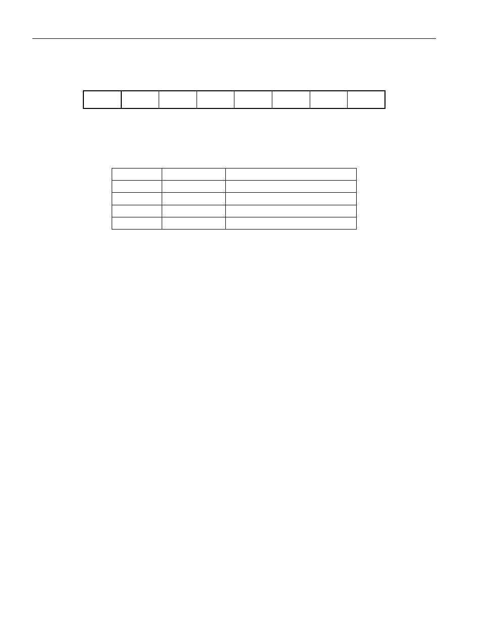
STATUS REGISTER FORMAT Figure 12
Address 01
bit 7
bit 6
bit 5
bit 4
bit 3
bit 2
bit 1
bit 0
CSTAT1
CSTAT0
PMOD
RNAOP
X
X
CINI
CTYPE
CSTAT1, CSTAT0
— Charge Status. The CSTAT1 and CSTAT0 bits indicate the status of charge per
the table below:
CSTAT1
CSTAT0
STATUS
0
0
No charge source present
0
1
Charge in progress
1
0
Charge source is present
1
1
Charge sequence completed
The charge sequence complete state (1, 1) is present until cleared by a write to the Status Register.
PMOD
— Sleep Mode Enable. A value of 1 in this bit enables the DS2770 to enter Sleep Mode when the
DQ line goes low for greater than two seconds and leaves Sleep Mode when the DQ line goes high. A
value of 0 disables DQ-related transitions into and out of Sleep Mode. The desired default value should
be set in bit 5 of address location 31h. The factory default of the PMOD bit is 0.
RNAOP
— Read Net Address Opcode. A value of 0 in this bit sets the opcode for the Read Net Address
command to 33h, while a 1 sets the opcode to 39h. The desired default value should be set in bit 4 of
address location 31h. The factory default of the RNAOP bit is 0.
CINI
— Charge Initiation Select. The CINI bit is used to determine the method of charge initiation that
will be allowed. A value of 0 indicates that charge may be started only upon use of the Start Charge [B5h]
command. A value of 1 indicates that charge may be started by either the Start Charge command, or by
the application of a charge source at the charge supply input pin, VCH. The desired default value should
be set in bit 1 of address location 31h. The factory default of the CINI bit is 0.
CTYPE
— Charge Type. The charge type bit indicates the Charge Mode that will be used during
charging. A 1 selects NiMH charger operation and a 0 selects rechargeable lithium charger operation. The
desired default value should be set in bit 0 of address location 31h. It is suggested that the EEPROM
block containing the Status Register initiation (location 31h) be locked once the CTYPE and other Status
Register bits are configured to avoid any possible unintended alterations during use. The factory default
of the CTYPE bit is 0.
X
— Reserved Bits.