Net address format figure 14, Crc generation – Rainbow Electronics DS2770 User Manual
Page 16
DS2770
16 of 27
NET ADDRESS FORMAT Figure 14
8-Bit CRC
48-Bit Serial Number
8-Bit Family
Code (2Eh)
CRC GENERATION
The DS2770 has an 8-bit CRC stored in the most significant byte of its 64-bit net address. To ensure
error-free transmission of the address, the host system can compute a CRC value from the first 56 bits of
the address and compare it to the CRC from the DS2770. The host system is responsible for verifying the
CRC value and taking action as a result. The DS2770 does not compare CRC values and does not prevent
a command sequence from proceeding as a result of a CRC mismatch. Proper use of the CRC can result
in a communication channel with a very high level of integrity.
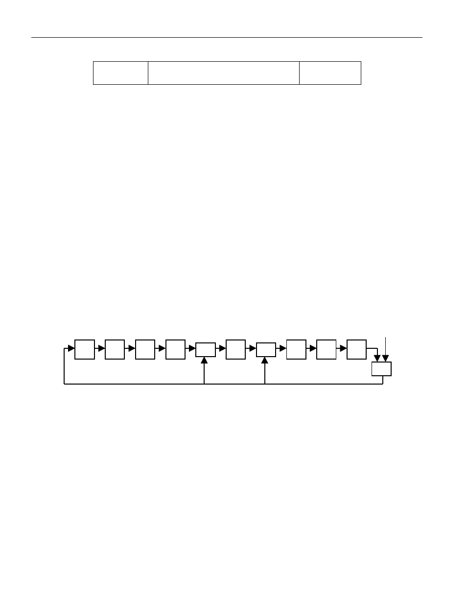
The 1-Wire CRC can be generated by the host using a circuit consisting of a Shift Register and XOR
gates as shown in Figure 15, or it can be generated in software. Additional information about the Dallas
1-Wire Cyclic Redundancy Check is available in Application Note 27, Understanding and Using Cyclic
Redundancy Checks with Dallas Semiconductor Touch Memory Products.
In Figure 15, the Shift Register bits are initialized to 0. Then, starting with the least significant bit of the
family code, one bit at a time is shifted in. After the 8
th
bit of the family code has been entered, the serial
number is entered. After the 48
th
bit of the serial number has been entered, the Shift Register contains the
CRC value.
1-WIRE CRC GENERATION BLOCK DIAGRAM Figure 15
HARDWARE CONFIGURATION
Because the 1-Wire bus has only a single line, it is important that each device on the bus be able to drive
it at the appropriate time. To facilitate this, each device attached to the 1-Wire bus must connect to the
bus with open-drain or tristate output drivers. The DS2770 uses an open-drain output driver as part of the
bidirectional interface circuitry shown in Figure 16. If a bidirectional pin is not available on the bus
master, separate output and input pins can be tied together.
The 1-Wire bus must have a pull-up resistor at the bus-master end of the bus. For short line lengths, the
value of this resistor should be approximately 5k
W. The idle state for the 1-Wire bus is high. If, for any
reason, a bus transaction must be suspended, the bus must be left in the idle state in order to properly
resume the transaction later. If the bus is left low for more than 120
ms, slave devices on the bus begin to
interpret the low period as a reset pulse, effectively terminating the transaction.
MSb
XOR
XOR
LSb
XOR
input