Pin configuration, Typical application circuit package information – Rainbow Electronics DS8314 User Manual
Page 17
DS8313/DS8314
Smart Card Interface
Maxim cannot assume responsibility for use of any circuitry other than circuitry entirely embodied in a Maxim product. No circuit patent licenses are
implied. Maxim reserves the right to change the circuitry and specifications without notice at any time.
Maxim Integrated Products, 120 San Gabriel Drive, Sunnyvale, CA 94086 408-737-7600 ____________________ 17
© 2009 Maxim Integrated Products
Maxim is a registered trademark of Maxim Integrated Products, Inc.
PACKAGE TYPE
PACKAGE CODE
DOCUMENT NO.
28 SO
W28+1
28 TSSOP
U28+1
1_8V
28
27
26
25
24
23
22
N.C.
N.C.
I/OIN
XTAL2
TOP VIEW
XTAL1
OFF
GND
21 V
DD
20 RSTIN
19 CMDVCC
18 V
DDA
(N.C.)
17 V
CC
16 RST
15 CLK
5V/3V
CLKDIV2
CLKDIV1
() INDICATES DS8314 ONLY.
N.C.
V
DDA
N.C.
N.C.
PRES
I/O
N.C.
N.C.
4
1
2
3
5
6
7
8
9
10
11
12
13
14
CGND
N.C.
TSSOP/SO
DS8313
DS8314
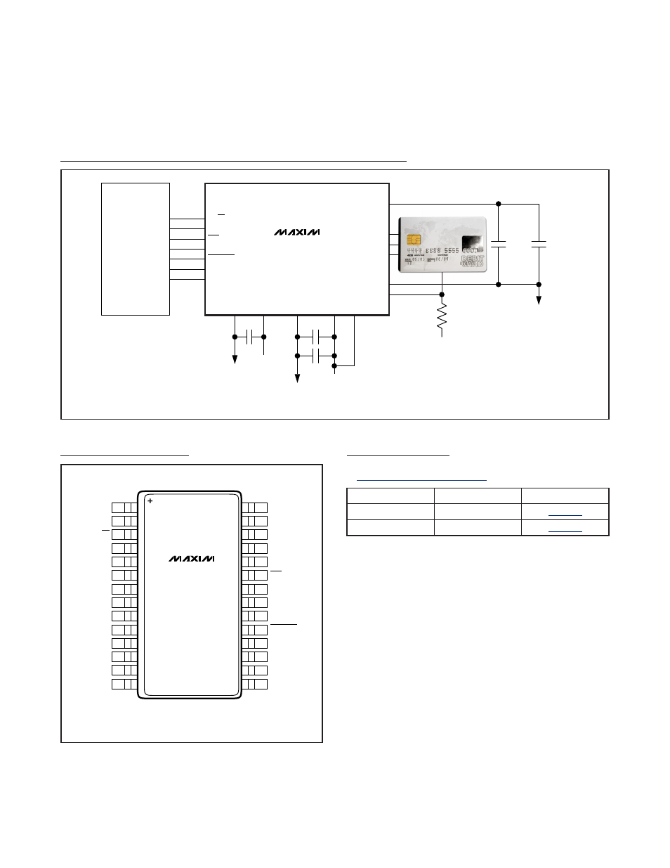
Pin Configuration
+3.3V
100k
Ω
*PLACE A 100nF CAPACITOR CLOSE TO DS8313 AND PLACE A 220nF CAPACITOR CLOSE TO CARD CONTACT.
GPIO
μC
...
...
GPIO
ISO_DATA
100nF*
220nF*
100nF
+3.3V
I/OIN
CMDVCC
...
RSTIN
ISO_CLOCK
CLKIN
OFF
1_8V
5V/3V
PRES
CGND
I/O
CLK
RST
V
CC
GND
V
DD
+10
μF
GND
V
DDA
V
DDA
100nF
+5.0V
DS8313
Typical Application Circuit
Package Information
For the latest package outline information and land patterns, go
to
www.maxim-ic.com/packages
.