Bus master circuit figure 12 – Rainbow Electronics DS2406 User Manual
Page 18
DS2406
18 of 31
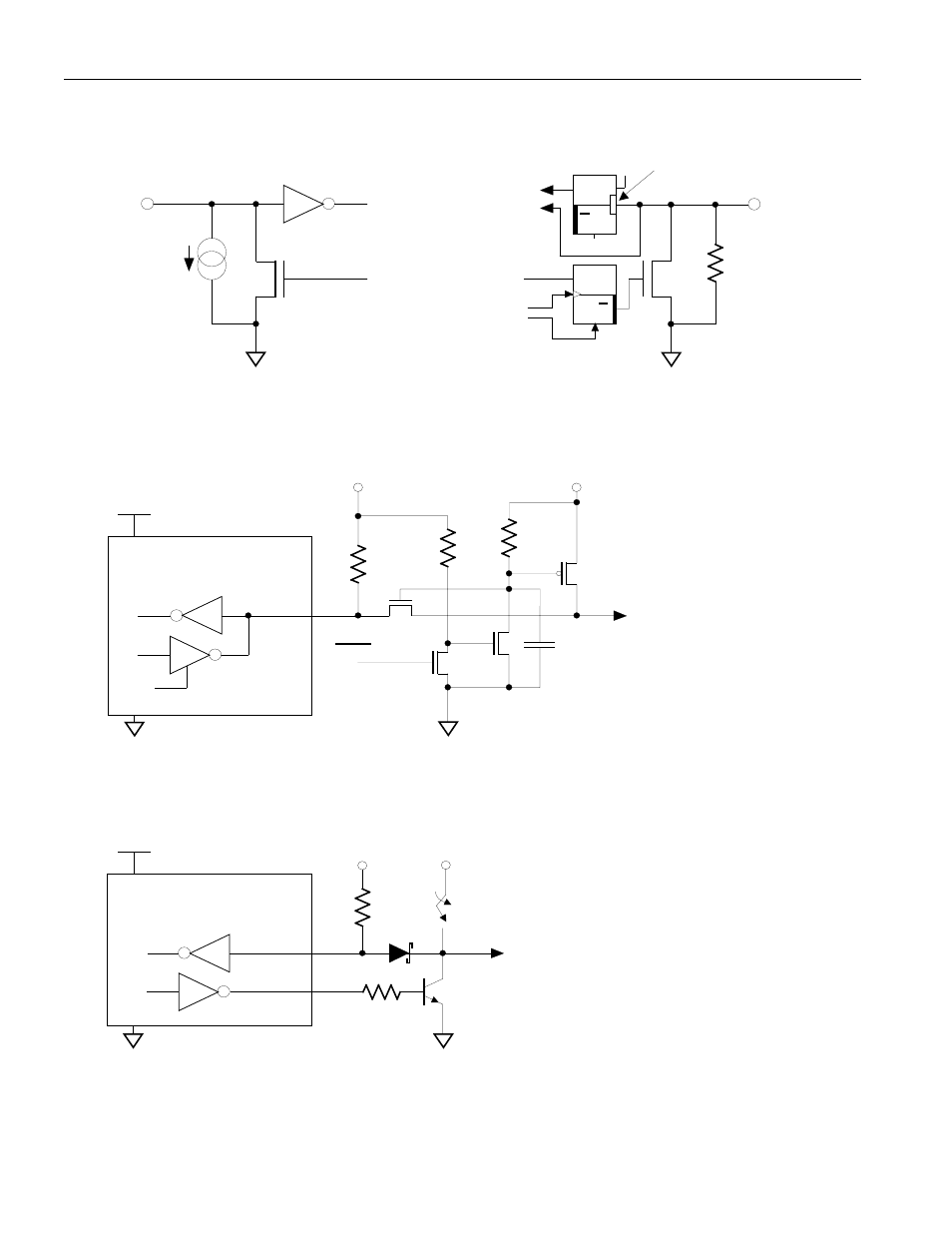
DS2406 EQUIVALENT CIRCUIT Figure 11
1-Wire Interface
PIO
Ground
PIO Channel
Reset
D
"1"
Q
Q
Activity
Latch
D Q
Q
1-Wire DATA
Channel
Flip-Flop
to PIO-
Control
10 M
W
Typ.
from PIO-
Control
R
Edge
Detector
DATA
RX
TX
100
W
MOSFET
Ground
5 µA
Typ.
BUS MASTER CIRCUIT Figure 12
A) Open Drain
12V
Open Drain
Port Pin
S
D
D
S
470 pF
D
S
PGM
D
S
2N7000
2N7000
2N7000
VP0300L
OR
VP0106N3
OR
BSS110
Capacitor added to reduce
coupling on data line due to
programming signal switching
VPUP
RX
TX
B) Standard TTL
TTL-Equivalent
Port Pins
5 k
W
12V
(10 mA min.)
to data connection
of DS2406
PROGRAMMING PULSE
The diode and programming circuit are not required if one does not intend to program the EPROM cells
VPUP
RX
TX
DD
V
5 k
W
to data connection
of DS2406
DD
V
DS5000 OR 8051-
EQUIVALENT
5 k
W
10 k
W
10 k
W
BUS MASTER
BUS MASTER
The interface is reduced to the
pull-up resistor if one does not intend to program the EPROM cells.
5k
W
- MAX16840 (1 page)
- MAX9258 (54 pages)
- MAX66140 (21 pages)
- MAX9393 (14 pages)
- MAX66040 (25 pages)
- MAX6981 (1 page)
- MAX6965 (23 pages)
- MAX66100 (16 pages)
- MAX9135 (19 pages)
- MAX66020 (25 pages)
- MAX17127 (22 pages)
- MAX13175E (38 pages)
- MAX16820 (10 pages)
- MAX13237E (16 pages)
- MAX13483E (19 pages)
- MAX13362 (14 pages)
- MAX13486E (16 pages)
- MAX7311 (17 pages)
- MAX8759 (31 pages)
- SCAN92LV090 (13 pages)
- MAX6973 (23 pages)
- MAX13047E (14 pages)
- MAX16831 (20 pages)
- MAX14770E (15 pages)
- MAX11835 (1 page)
- MAX9621 (14 pages)
- MAX9217 (16 pages)
- MAX16841 (18 pages)
- MAX16834 (22 pages)
- MAX7315 (27 pages)
- MAX8645Y (15 pages)
- MAX6975 (23 pages)
- MAX6971 (12 pages)
- MAX3028 (21 pages)
- MAX9395 (13 pages)
- MAX7313 (27 pages)
- MAX6970 (1 page)
- MAX4821 (13 pages)
- MAX4895E (8 pages)
- MAX16823 (13 pages)
- MAX6963 (34 pages)
- MAX9216 (17 pages)
- MAX66000 (21 pages)
- MAX66120 (24 pages)
- MAX13223E (11 pages)