Rainbow Electronics DS28EA00 User Manual
Page 9
DS28EA00 1-Wire Digital Thermometer with Sequence Detect and PIO
9 of 29
PIO Structure
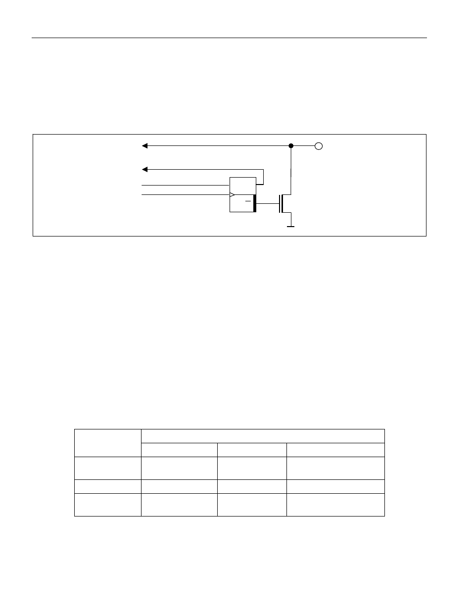
Each PIO consists of an open-drain pulldown transistor and an input path to read the pin state. The transistor is
controlled by the PIO Output Latch, as shown in Figure 6. The Device Function Control unit connects the PIOs
logically to the 1-Wire interface. PIOA has a pullup path to internal V
DD
to facilitate the sequence detect function
(see Figure 1) in conjunction with the Chain command; PIOB is truely an open-drain structure. The power-on
default state of the PIO output transistors is off; high-impedance on-chip resistors (not shown in the graphic) pull
the PIO pins to internal V
DD
.
Figure 6. PIO Simplified Logic Diagram
PIO Pin
State
PIO Pin
PIO Out-
put Latch
PIO Output
Latch State.
Q
D
Q
PIO Data
PIO Clock
CLOCK
Chain Function
The chain function is a feature that allows the 1-Wire master to discover the physical sequence of devices that are
wired as a linear network (“chain”). This is particularly convenient for devices that are installed at equal spacing
along a long cable, e.g., to measure temperatures at different locations inside a storage tower or tank. Without
chain function, the master needs a lookup table to correlate registration number to the physical location.
The chain function requires two pins, an input (EN\) to enable a device to respond during the discovery and an
output (DONE\) to inform the next device in the chain that the discovery of its neighbor is done. The two general
purpose ports of the DS28EA00 are re-used for the chain function. PIOB functions as EN\ input and PIOA
generates the DONE\ signal, which is connected to the EN\ input of the next device, as shown in the typical
operating circuit on page 1. The EN\ input of the first device in the chain needs to be hardwired to GND or logic ‘0’
must be applied for the duration of the sequence discovery process. Besides the two pins, the sequence discovery
relies on the Conditional Read ROM command.
For the chain function and normal PIO operation to coexist, the DS28EA00 distinguishes three chain states, OFF,
ON, and DONE. The transition from one chain state to another is controlled through the Chain command. Table 2
summarizes the chain states and the specific behavior of the PIO pins.
Table 2. Chain States
DEVICE BEHAVIOR
CHAIN STATE
PIOB (EN\)
PIOA (DONE\) Conditional
Read
ROM
OFF (default)
PIO (high
impedance)
PIO (high
impedance)
Not recognized
ON
EN\ input
Pullup on
Recognized if EN\ is ‘0’
DONE
No function
Pulldown on (DO\
logic ‘0’)
Not recognized
The power-on default chain state is OFF, where PIOA and PIOB are solely controlled through the PIO Access
Read and Write commands. In the chain ON state PIOA is pulled high to the device’s internal V
DD
supply through a
~40k
Ω resistor, applying a logic ‘1’ to the PIOB (EN\) pin of the next device. Only in the ON state does a
DS28EA00 respond to the Conditional Read ROM command, provided its EN\ is at logic ‘0’. After a device’s ROM