Table 1. temperature/data relationship – Rainbow Electronics DS28EA00 User Manual
Page 8
DS28EA00 1-Wire Digital Thermometer with Sequence Detect and PIO
8 of 29
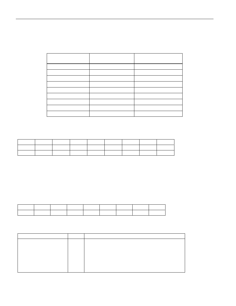
The temperature reading is in °C using a 16-bit sign-extended two’s complement format. Table 1 shows examples
of temperature and the corresponding data for 12-bit resolution. With two’s complement, the sign bit is set if the
value is negative. If the device is configured for 12-bit resolution, all bits in the LS byte are valid; for a reduced
resolution, bit 0 (11 bit mode), bits 0 to 1 (10 bit mode), and bits 0 to 2 (9 bit mode) are undefined.
Table 1. Temperature/Data Relationship
TEMPERATURE
DIGITAL OUTPUT
(BINARY)
DIGITAL OUTPUT
(HEX)
+85°C*
0000 0101 0101 0000
0550h
+25.0625°C
0000 0001 1001 0001
0191h
+10.125°C
0000 0000 1010 0010
00A2h
+0.5°C
0000 0000 0000 1000
0008h
0°C
0000 0000 0000 0000
0000h
-0.5°C
1111 1111 1111 1000
FFF8h
-10.125°C
1111 1111 0101 1110
FF5Eh
-25.0625°C
1111 1110 0110 1111
FE6Fh
-40°C
1111 1101 1000 0000
FD80h
*The power-on reset value of the temperature readout register is +85°C.
Temperature Alarm Registers
ADDR
bit 7
bit 6
bit 5
bit 4
bit 3
bit 2
bit 1
bit 0
2 S 2
6
2
5
2
4
2
3
2
2
2
1
2
0
High Alarm (TH)
3 S 2
6
2
5
2
4
2
3
2
2
2
1
2
0
Low Alarm (TL)
The result of a temperature conversion is automatically compared to the values in the alarm registers to determine
whether an alarm condition exists. Alarm thresholds are represented as two’s complement number. With 8 bits
available for sign and value, alarm thresholds can be set in increments of 1°C. An alarm condition exists if a
temperature conversion results in a value that is either higher than or equal to the value stored in the TH register
or lower than or equal to the value stored in the TL register. If a temperature alarm condition exists, the device
will respond to the Conditional Search command. The alarm condition is cleared if a subsequent temperature
conversion results in a temperature reading within the boundaries defined by the data in the TH and TL registers.
Configuration Register
ADDR
b7 b6 b5 b4 b3 b2 b1 b0
4 0 R1
R0 1 1 1 1 1
The functional assignments of the individual bits are explained in the table below. Bits 0 to 4 and bit 7 have no
function; they cannot be changed by the user. As a factory default, the device operates in 12-bit resolution.
BIT DESCRIPTION
BIT(S)
DEFINITION
R0, R1: Temperature
Converter Resolution
b5, b6
These bits control the resolution of the temperature
converter. The codes are as follows:
R1 R0
0
0
9 bits
0
1
10 bits
1
0
11 bits
1 1
12
bits