Wire bus system, Hardware configuration, Transaction sequence – Rainbow Electronics DS28EA00 User Manual
Page 18: Initialization
DS28EA00 1-Wire Digital Thermometer with Sequence Detect and PIO
18 of 29
1-Wire BUS SYSTEM
The 1-Wire bus is a system that has a single bus master and one or more slaves. In all instances the DS28EA00 is
a slave device. The bus master is typically a microcontroller. The discussion of this bus system is broken down into
three topics: hardware configuration, transaction sequence, and 1-Wire signaling (signal types and timing). The
1-Wire protocol defines bus transactions in terms of the bus state during specific time slots, which are initiated on
the falling edge of sync pulses from the bus master.
HARDWARE CONFIGURATION
The 1-Wire bus has only a single line by definition; it is important that each device on the bus be able to drive it at
the appropriate time. To facilitate this, each device attached to the 1-Wire bus must have open-drain or tri-state
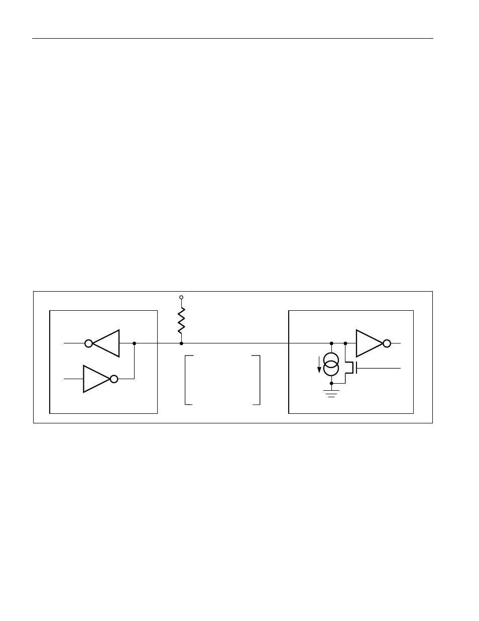
outputs. The 1-Wire port of the DS28EA00 is open drain with an internal circuit equivalent to that shown in Figure
11.
A multidrop bus consists of a 1-Wire bus with multiple slaves attached. The DS28EA00 supports both a Standard
and Overdrive communication speed of 15.3kbps (max) and 125kbps (max), respectively. Note that legacy 1-Wire
products support a standard communication speed of 16.3kbps and Overdrive of 142kbps. The slightly reduced
rates for the DS28EA00 are a result of additional recovery times, which in turn were driven by a 1-Wire physical
interface enhancement to improve noise immunity. The value of the pullup resistor primarily depends on the
network size and load conditions. The DS28EA00 requires a pullup resistor of 2.2k
Ω (max) at any speed.
The idle state for the 1-Wire bus is high. If for any reason a transaction needs to be suspended, the bus MUST be
left in the idle state if the transaction is to resume. If this does not occur and the bus is left low for more than 16µs
(Overdrive speed) or more than 120µs (standard speed), one or more devices on the bus may be reset.
Figure 11. Hardware Configuration
Open-Drain
Port Pin
RX = RECEIVE
TX = TRANSMIT
100
Ω
MOSFET
V
PUP
RX
TX
TX
RX
DATA
I
L
BUS MASTER
DS28EA00 1-Wire PORT
R
PUP
TRANSACTION SEQUENCE
The protocol for accessing the DS28EA00 through the 1-Wire port is as follows:
Initialization
ROM Function Command
Control Function Command
Transaction/Data
INITIALIZATION
All transactions on the 1-Wire bus begin with an initialization sequence. The initialization sequence consists of a
reset pulse transmitted by the bus master followed by presence pulse(s) transmitted by the slave(s). The presence
pulse lets the bus master know that the DS28EA00 is on the bus and is ready to operate. For more details, see the
1-Wire Signaling section.