Absolute maximum ratings, Electrical characteristics – Rainbow Electronics DS28EA00 User Manual
Page 2
DS28EA00 1-Wire Digital Thermometer with Sequence Detect and PIO
2 of 29
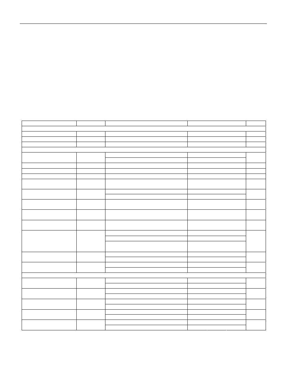
ABSOLUTE MAXIMUM RATINGS
IO Voltage to GND
-0.5V, +6V
IO Sink Current
20mA
Maximum PIOA or PIOB Pin Current
20mA
Maximum Current Through GND Pin
40mA
Operating Temperature Range
-40°C to +85°C
Junction Temperature
+150°C
Storage Temperature Range
-40°C to +85°C
Soldering Temperature
See IPC/JEDEC J-STD-020
Stresses beyond those listed under “Absolute Maximum Ratings” may cause permanent damage to the device. These are stress ratings only,
and functional operation of the device at these or any other conditions beyond those indicated in the operational sections of the specifications is
not implied. Exposure to the absolute maximum rating conditions for extended periods may affect device.
ELECTRICAL CHARACTERISTICS
(T
A
= -40°C to +85°C; see Note 1)
PARAMETER SYMBOL
CONDITIONS
MIN
TYP
MAX
UNITS
Power Supply
Supply Voltage
V
DD
(Note
2)
3.0 5.5 V
Supply Current (Note 5)
I
DD
V
DD
= 5.5V
1.5
mA
Standby Current
I
DDS
V
DD
= 5.5V
1.5
µA
IO Pin General Data
Local power
3.0
V
DD
1-Wire Pullup Voltage
(Note 2)
V
PUP
Parasite
power
3.0 5.5
V
1-Wire Pullup Resistance
R
PUP
(Notes 2, 3)
0.3 2.2
k
Ω
Input Capacitance
C
IO
(Notes 4, 5)
1000
pF
Input Load Current
I
L
IO pin at V
PUP
0.1 1.5
µA
High-to-Low Switching
Threshold
V
TL
(Notes 5, 6, 7)
0.46
V
PUP
-
1.9V
V
Parasite powered
0.5
Input Low Voltage (Notes
2, 8)
V
IL
V
DD
powered (Note 5)
0.7
V
Low-to-High Switching
Threshold (Notes 5, 6, 9)
V
TH
Parasite power
1.0
V
PUP
-
1.1V
V
Switching Hysteresis
(Notes 5, 6, 10)
V
HY
Parasite power
0.21
1.7
V
Output Low Voltage
(Note 11)
V
OL
At 4mA
0.4
V
Standard speed, R
PUP
= 2.2k
Ω
5
Overdrive speed, R
PUP
= 2.2k
Ω
2
Recovery Time
(Notes 2, 12)
t
REC
Overdrive speed, directly prior to reset
pulse; R
PUP
= 2.2k
Ω
5
µs
Standard
speed
0.5 5.0
Rising-Edge Hold-Off Time
(Notes 5, 13)
t
REH
Overdrive speed
Not applicable (0)
µs
Standard speed
65
Timeslot Duration
(Notes 2, 14)
t
SLOT
Overdrive speed
8
µs
IO Pin, 1-Wire Reset, Presence Detect Cycle
Standard speed
480
640
Reset Low Time (Note 2)
t
RSTL
Overdrive
speed
48 80
µs
Standard
speed
15 60
Presence-Detect High
Time
t
PDH
Overdrive speed
2
6
µs
Standard speed
1.125
8.1
Presence-Detect Fall Time
(Notes 5, 15)
t
FPD
Overdrive speed
0
1.3
µs
Standard speed
60
240
Presence-Detect Low
Time
t
PDL
Overdrive speed
8
24
µs
Standard speed
68.1
75
Presence-Detect Sample
Time (Notes 2,16)
t
MSP
Overdrive speed
7.3
10
µs