Figure 4. 1-wire crc generator, Register detailed description – Rainbow Electronics DS28EA00 User Manual
Page 7
DS28EA00 1-Wire Digital Thermometer with Sequence Detect and PIO
7 of 29
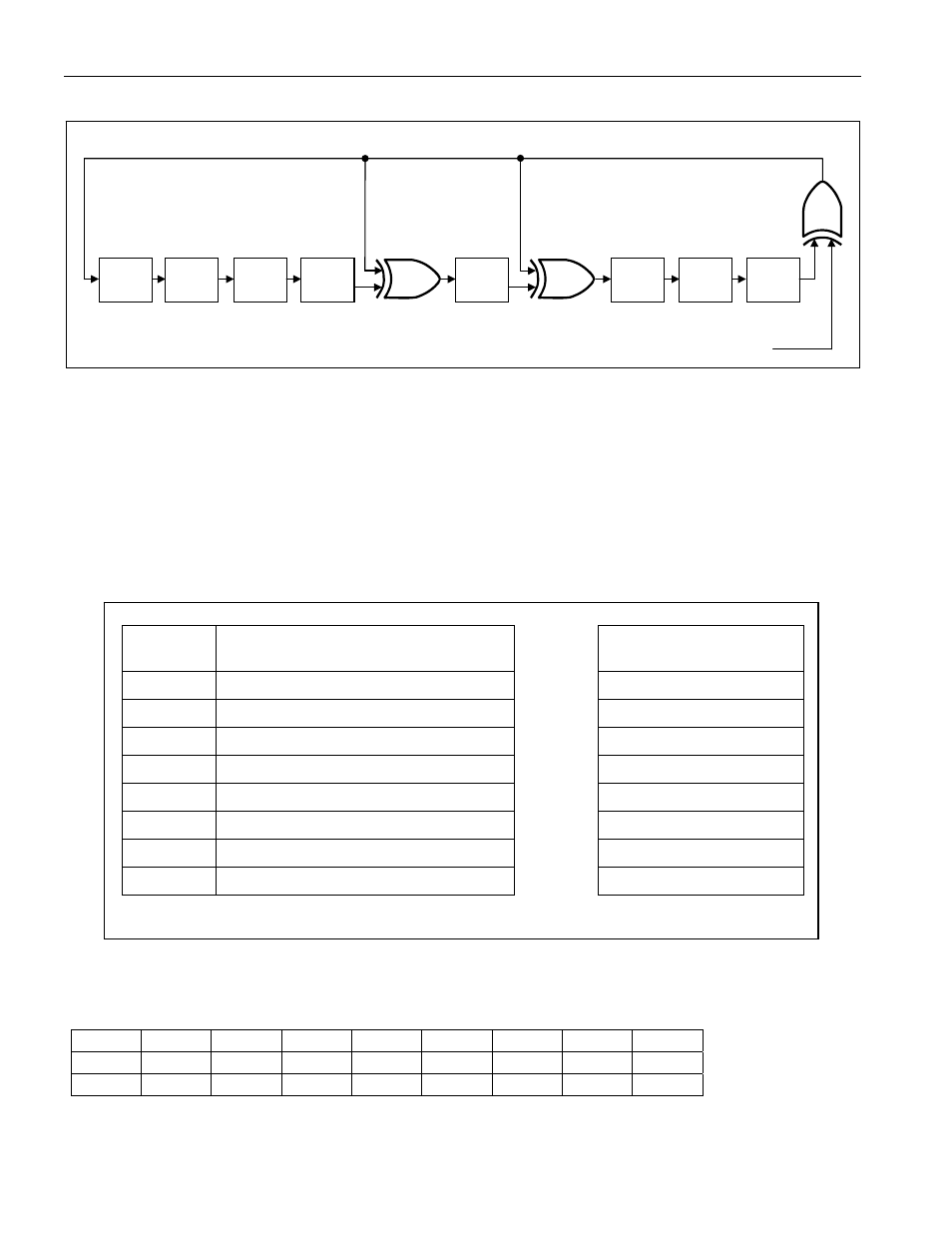
Figure 4. 1-Wire CRC Generator
X
0
X
1
X
2
X
3
X
4
X
5
X
6
X
7
X
8
Polynomial = X
8
+ X
5
+ X
4
+ 1
1
st
STAGE
2
nd
STAGE
3
rd
STAGE
4
th
STAGE
6
th
STAGE
5
th
STAGE
7
th
STAGE
8
th
STAGE
INPUT DATA
Memory Description
The memory of the DS28EA00 is shown in Figure 5. It consists of an 8-byte scratchpad and 3 bytes of backup
EEPROM. The first two bytes form the temperature readout register, which is updated after a temperature
conversion and is read-only. The next 3 bytes are user-writeable; they contain the Temperature High (TH) and the
Temperature Low (TL) alarm register and a configuration register. The remaining 3 bytes are “reserved”. They
power up with constant data and cannot be written by the user. The TH, TL, and configuration register data in the
scratchpad control the resolution of a temperature conversion and decide whether a temperature is considered as
“alarming”. TH, TL, and configuration can be copied to the EEPROM to become nonvolatile (NV). The scratchpad
is automatically loaded with EEPROM data when the DS28EA00 powers up.
Figure 5. Memory Map
BYTE
ADDRESS
SCRATCHPAD (POWER-UP STATE)
BACKUP
EEPROM
0 Temperature
LSB
(50h)
N/A
1 Temperature
MSB
(05h)
N/A
2
TH Register or User Byte 1*
<-------->
TH Register or User Byte 1
3
TL Register or User Byte 2*
<-------->
TL Register or User Byte 2
4 Configuration
Register*
<--------> Configuration
Register
5 Reserved
(FFh)
N/A
6 Reserved
(0Ch)
N/A
7 Reserved
(10h)
N/A
*Power-up state depends on value(s) stored in EEPROM.
Register Detailed Description
Temperature Readout Register
ADDR
bit 7
bit 6
bit 5
bit 4
bit 3
bit 2
bit 1
bit 0
0 2
3
2
2
2
1
2
0
2
-1
2
-2
2
-3
2
-4
LS Byte
1 S S S S S 2
6
2
5
2
4
MS Byte