Ac electrical characteristics, Electrical characteristics – Rainbow Electronics DS92001 User Manual
Page 3
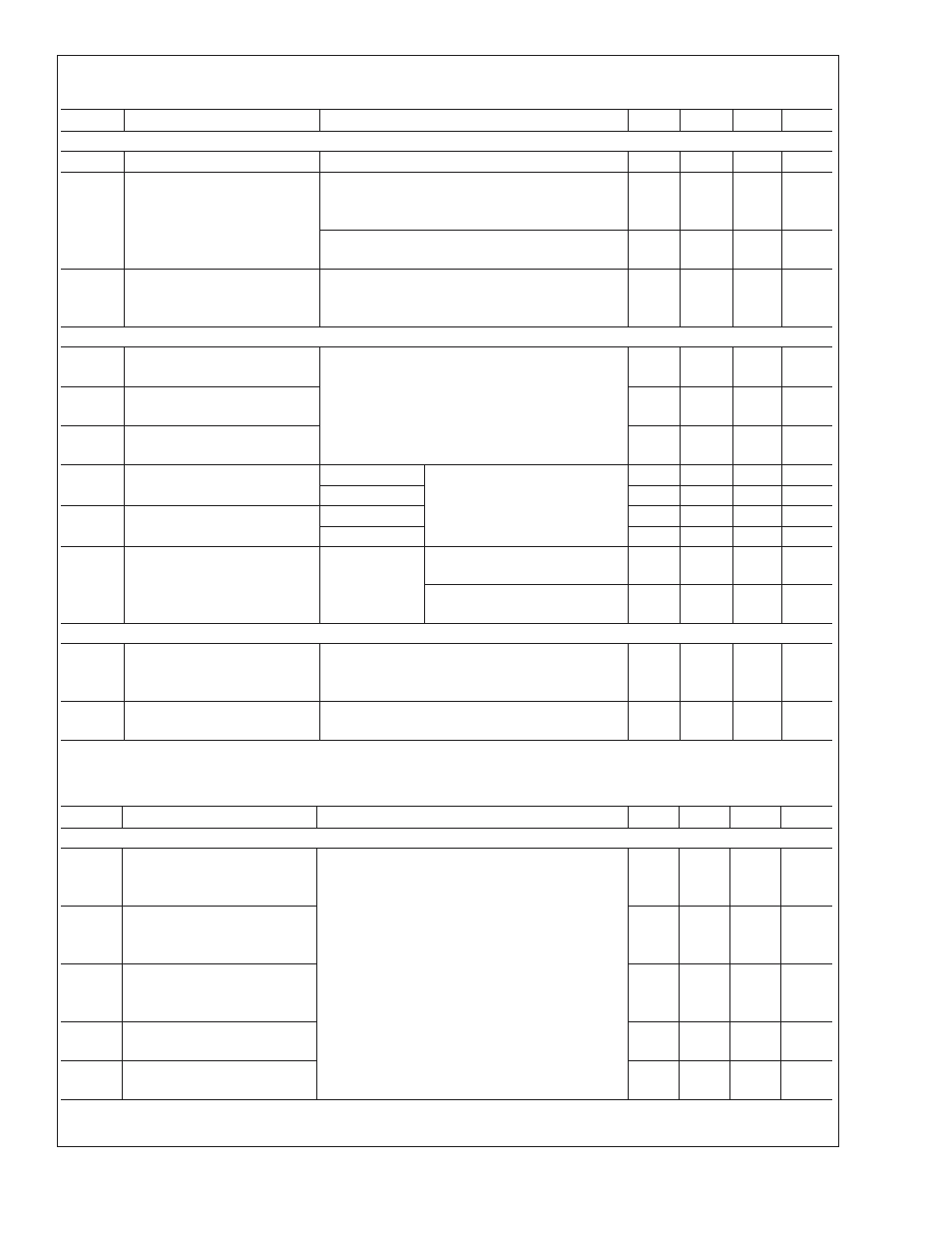
Electrical Characteristics
(Continued)
Over recommended operating supply and temperature ranges unless otherwise specified. (Notes 2, 3)
Symbol
Parameter
Conditions
Min
Typ
Max
Units
BLVDS OUTPUT DC SPECIFICATIONS (OUT)
I
OFF
Power-Off Leakage Current
V
CC
= 0V or Open Circuit, V
OUT
= 3.6V
−20
±
5
+20
µA
I
OS1
Output Short Circuit Current
EN = V
CC
, V
CM
= 1.2V,V
ID
= 200mV, V
OUT+
= 0V,
or
V
ID
= −200mV, V
CM
= 1.2V, V
OUT−
= 0V
−30
−60
mA
V
ID
= −200mV, V
CM
= 1.2V, V
OUT+
= V
CC
, or
V
ID
= 200mV, V
CM
=1.2V, V
OUT−
= V
CC
53
80
mA
I
OSD
Differential Output Short Circuit
Current (Note 4)
EN = V
CC
, V
ID
= |200mV|, V
CM
. = 1.2V, V
OD
= 0V
(connect true and complement outputs through a
current meter)
|30|
|42|
mA
B/LVDS RECEIVER DC SPECIFICATIONS (IN)
V
TH
Differential Input High
Threshold (Note 5)
V
CM
= +0.05V, +1.2V or +3.25V
−30
−5
mV
V
TL
Differential Input Low
Threshold (Note 5)
−70
−30
mV
V
CMR
Common Mode Voltage Range
|V
ID
|/2
V
CC
−|V
ID
|/2
V
I
IN
Input Current
V
IN
= V
CC
V
CC
= 3.6V or 0V
|1.5|
|20|
µA
V
IN
= 0V
|1.5|
|20|
µA
∆I
IN
Change in Magnitude of I
IN
V
IN
= V
CC
1
6
µA
V
IN
= 0V
1
6
µA
V
FSOD
Fail-safe BLVDS Outputs
(OUT+ is a more positive
voltage than OUT−)
Inputs open,
shorted, or
terminated
R
L
= 27
Ω
250
350
500
mV
R
L
= 50
Ω
350
450
600
mV
SUPPLY CURRENT
I
CCD
Total Dynamic Supply Current
(includes load current)
EN = V
CC
, R
L
= 27
Ω or 50Ω, C
L
= 15 pF,
Freq. = 200MHz 50% duty cycle,
V
ID
= 200mV, V
CM
= 1.2V
50
65
mA
I
CCZ
TRI-STATE Supply Current
EN = 0V,Freq. = 200MHz 50% duty cycle,
V
ID
= 200mV, V
CM
= 1.2V
36
46
mA
AC Electrical Characteristics
Over recommended operating supply and temperature ranges unless otherwise specified. (Note 3)
Symbol
Parameter
Conditions
Min
Typ
Max
Units
LVDS OUTPUT AC SPECIFICATIONS (OUT)
t
PHLD
Differential Propagation Delay
High to Low
V
ID
= 200mV, V
CM
= 1.2V,
R
L
= 27
Ω or 50Ω, C
L
= 15pF
1.0
1.4
2.0
ns
t
PLHD
Differential Propagation Delay
Low to High
1.0
1.4
2.0
ns
t
SKD1
Pulse Skew |t
PLHD
− t
PHLD
|
(measure of duty cycle)
(Notes 5, 6)
0
20
200
ps
t
SKD3
Part-to-Part Skew (Note 5)
0
200
300
ps
t
SKD4
Part-to-Part Skew (Note 5)
0
1
ns
DS92001
www.national.com
3