Battery operate mode, Battery operate mode figure 17, Device operation modes – Rainbow Electronics DS2404 User Manual
Page 23
DS2404
23 of 29
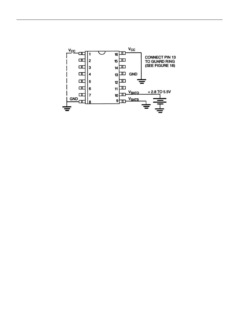
Battery Operate Mode
Figure 17 shows the necessary connections for operating the DS2404 in Battery Operate mode.
BATTERY OPERATE MODE Figure 17
V
CC
Pin 1 & 16
Ground
V
BATB
Pin
9
Ground
V
BATO
Pin 10
2.8 to 5.5V
The V
BATO
pin is normally connected to any standard 3 V lithium cell or other energy source. The Battery
Operate mode also minimizes the power-consumption in applications where battery backup is not
required and the V
BATO
lead is directly connected to the system’s 5V supply.
NOTE:
In Battery Operate mode, the voltage on DQ must never exceed the voltage on V
BATO
if the 3-wire
interface is used. This restriction does not apply to the 1-Wire interface.
DEVICE OPERATION MODES
With its two ports and two power modes the DS2404 can be operated in several ways. While the
maximum voltage on the 1-Wire port (I/O) is always 6V, the maximum voltage on the 3-wire port (DQ)
depends on the power mode and actual operating voltage. A particular port is selected by setting the
control lines to a state that makes the other port inactive. See Table 1 for details.
When using the 3-wire port only and the DS2404 is wired for V
CC
Operate Mode (Battery Backed) the
1 Wire I/O pin can be used as counter input. This mode requires that the I/O lead is connected to V
CC
through a 5k
W (typical) resistor. To enable communication through the 3-wire port a reset/presence
sequence has to be performed on the 1-Wire port after the system has powered up.