Rainbow Electronics DS2404 User Manual
Page 14
DS2404
14 of 29
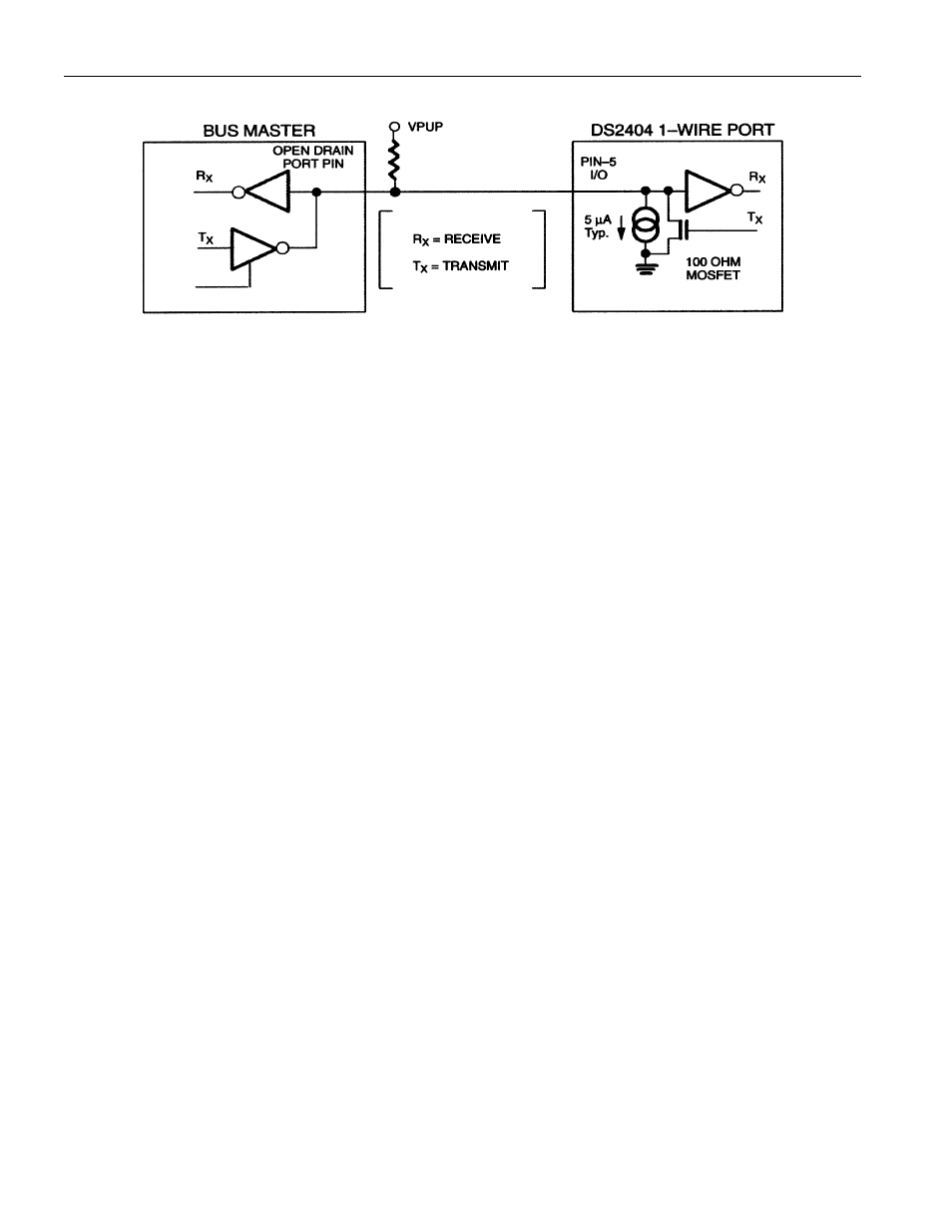
HARDWARE CONFIGURATION Figure 8
NOTE:
Depending on 1-Wire communication speed and bus load characteristics, the optimal pull-up resistor
value will be in the 1.5 k
W range to 5 kW range.
TRANSACTION SEQUENCE
The protocol for accessing the DS2404 via the 1-Wire port is as follows:
§ Initialization
§ ROM Function Command
§ Memory Function Command
§ Transaction/Data
INITIALIZATION
All transactions on the 1-Wire bus begin with an initialization sequence. The initialization sequence
consists of a reset pulse transmitted by the bus master followed by presence pulse(s) transmitted by the
slave(s). The presence pulse lets the bus master know that the DS2404 is on the bus and is ready to
operate. For more details, see the “1-Wire Signaling” section.
ROM FUNCTION COMMANDS
Once the bus master has detected a presence, it can issue one of the five ROM function commands. All
ROM function commands are eight bits long. A list of these commands follows (refer to flowchart in
Figure 9):
Read ROM [33h]
This command allows the bus master to read the DS2404’s 8-bit family code, unique 48-bit serial
number, and 8-bit CRC. This command can only be used if there is a single DS2404 on the bus. If more
than one slave is present on the bus, a data collision will occur when all slaves try to transmit at the same
time (open drain will produce a wired-AND result). The resultant family code and 48-bit serial number
will usually result in a mismatch of the CRC.
See
Note