Power control – Rainbow Electronics DS2404 User Manual
Page 21
DS2404
21 of 29
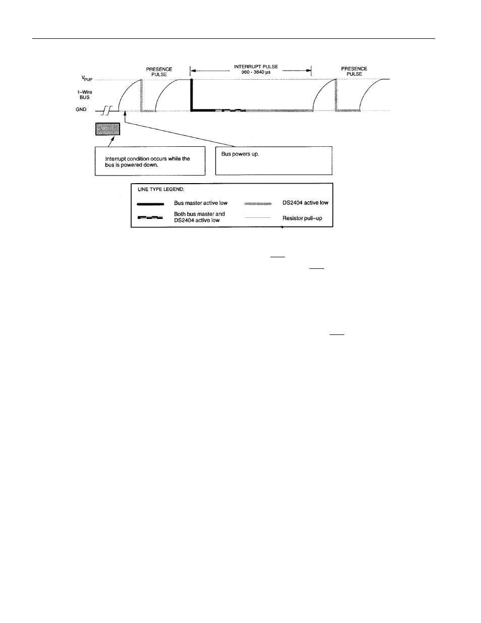
TYPE 2 INTERRUPT (SPECIAL CASE) Figure 15
3-WIRE I/O COMMUNICATIONS
The 3–wire bus is comprised of three signals. These are the
RST
(reset) signal, the CLK (clock) signal,
and the DQ (data) signal. All data transfers are initiated by driving the
RST
input high. Driving the RST
input low terminates communication. (See Figures 19 and 20.)
A clock cycle is a sequence of a falling edge followed by a rising edge. For data inputs, the data must be
valid during the rising edge of a clock cycle. Command bits and data bits are input on the rising edge of
the clock and data bits are output on the falling edge of the clock. When reading data from the DS2404,
the DQ pin goes to a high impedance state while the clock is high. Taking
RST
low will terminate any
communication and cause the DQ pin to go to a high impedance state.
POWER CONTROL
There are two methods of supplying power to the DS2404, V
CC
Operate mode with battery backup and
Battery Operate mode. If the DS2404 is used in an application where battery backup is not desired, the
part must be wired for Battery Operate mode.