Read time slots, Read/write time slot timing diagram figure 11, And t – Rainbow Electronics DS18S20 User Manual
Page 13
DS18S20
13 of 21
READ TIME SLOTS
The DS18S20 can only transmit data to the master when the master issues read time slots. Therefore, the
master must generate read time slots immediately after issuing a Read Scratchpad [BEh] or Read Power
Supply [B4h] command, so that the DS18S20 can provide the requested data. In addition, the master can
generate read time slots after issuing Convert T [44h] or Recall E
2
[B8h] commands to find out the status
of the operation as explained in the DS18S20 FUNCTION COMMAND section.
All read time slots must be a minimum of 60
µ
s in duration with a minimum of a 1
µ
s recovery time
between slots. A read time slot is initiated by the master device pulling the 1-wire bus low for a
minimum of 1
µ
s and then releasing the bus (see Figure 11). After the master initiates the read time slot,
the DS18S20 will begin transmitting a 1 or 0 on bus. The DS18S20 transmits a 1 by leaving the bus high
and transmits a 0 by pulling the bus low. When transmitting a 0, the DS18S20 will release the bus by the
end of the time slot, and the bus will be pulled back to its high idle state by the pullup resister. Output
data from the DS18S20 is valid for 15
µ
s after the falling edge that initiated the read time slot. Therefore,
the master must release the bus and then sample the bus state within 15
µ
s from the start of the slot.
Figure 12 illustrates that the sum of T
INIT
, T
RC
, and T
SAMPLE
must be less than 15
µ
s for a read time slot.
Figure 13 shows that system timing margin is maximized by keeping T
INIT
and T
RC
as short as possible
and by locating the master sample time during read time slots towards the end of the 15
µ
s period.
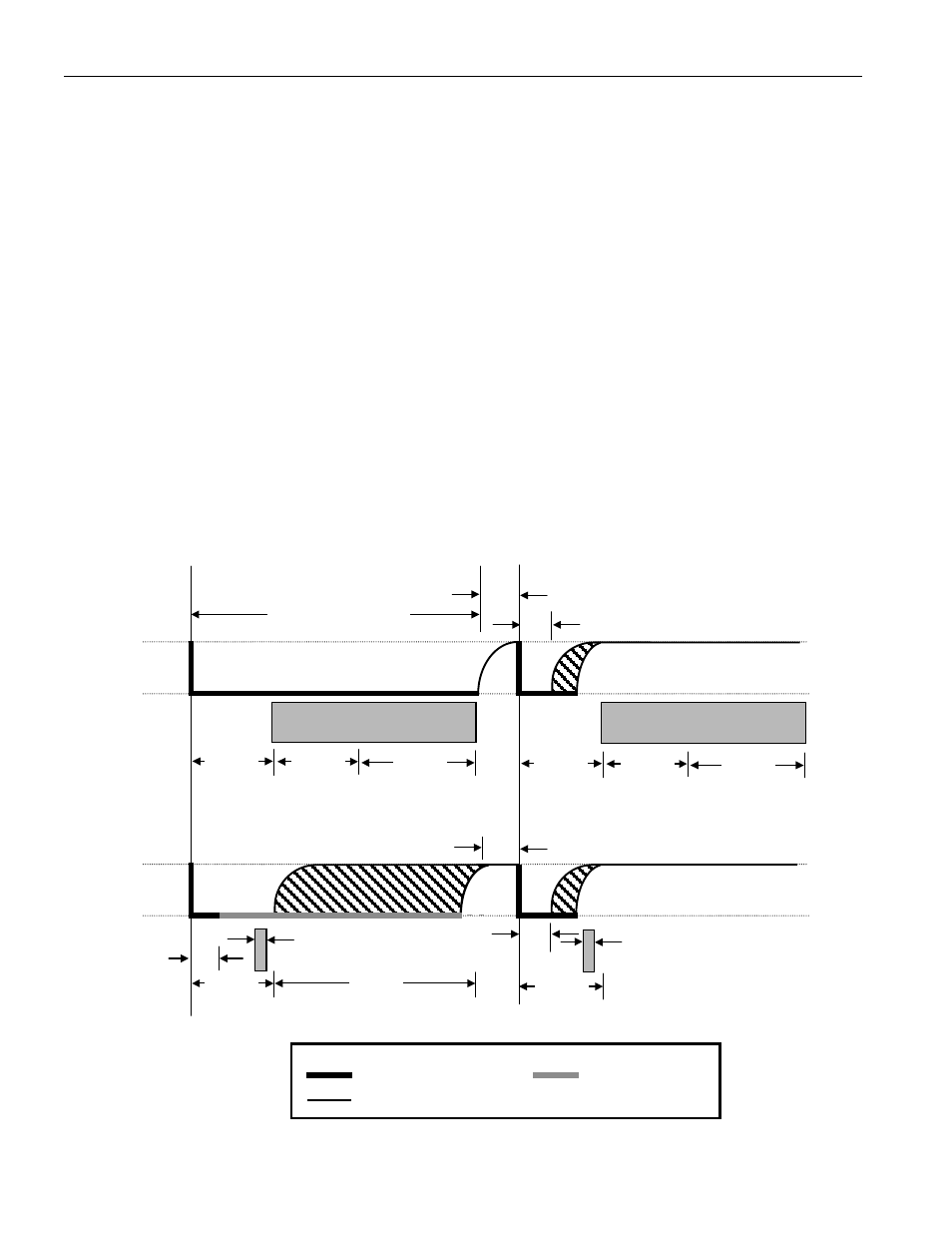
READ/WRITE TIME SLOT TIMING DIAGRAM Figure 11
45
µµµµ
s
15
µµµµ
s
V
PU
GND
1-WIRE BUS
60
µµµµ
s < T
X
“0” < 120
1
µµµµ
s < T
REC
<
∞
DS18S20
Samples
MIN TYP MAX
15
µµµµ
s
30
µµµµ
s
> 1
µµµµ
s
MASTER WRITE “0” SLOT
MASTER WRITE “1” SLOT
V
PU
GND
1-WIRE BUS
15
µµµµ
s
MASTER READ “0” SLOT
MASTER READ “1” SLOT
Master samples
Master samples
START
OF SLOT
START
OF SLOT
> 1
µµµµ
s
1
µµµµ
s < T
REC
<
∞
15
µµµµ
s
15
µµµµ
s
30
µµµµ
s
15
µµµµ
s
DS18S20
Samples
MIN TYP MAX
> 1
µµµµ
s
LINE TYPE LEGEND
Bus master pulling low
DS18S20 pulling low
Resistor
pullup