Rainbow Electronics DS18S20 User Manual
Digital thermometer, Features, Pin assignment
1 of 21
043001
FEATURES
•
Unique 1-wire interface requires only one
port pin for communication
•
Each device has a unique 64-bit serial code
stored in an on-board ROM
•
Multi-drop capability simplifies distributed
temperature sensing applications
•
Requires no external components
•
Can be powered from data line. Power supply
range is 3.0V to 5.5V
•
Measures temperatures from –55°C to
+125°C (–67°F to +257°F)
• ±
0.5
°
C accuracy from –10°C to +85°C
•
9-bit thermometer resolution
•
Converts temperature in 750 ms (max.)
•
User-definable nonvolatile alarm settings
•
Alarm search command identifies and
addresses devices whose temperature is
outside of programmed limits (temperature
alarm condition)
•
Applications include thermostatic controls,
industrial systems, consumer products,
thermometers, or any thermally sensitive
system
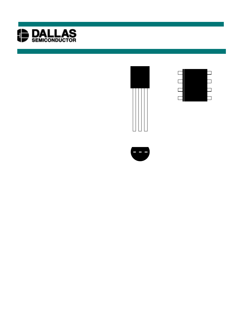
PIN ASSIGNMENT
PIN DESCRIPTION
GND -
Ground
DQ -
Data
In/Out
V
DD
- Power Supply Voltage
NC
- No Connect
DESCRIPTION
The DS18S20 Digital Thermometer provides 9–bit centigrade temperature measurements and has an
alarm function with nonvolatile user-programmable upper and lower trigger points. The DS18S20
communicates over a 1-wire bus that by definition requires only one data line (and ground) for
communication with a central microprocessor. It has an operating temperature range of –55°C to +125°C
and is accurate to
±
0.5
°
C over the range of –10°C to +85°C. In addition, the DS18S20 can derive power
directly from the data line (“parasite power”), eliminating the need for an external power supply.
Each DS18S20 has a unique 64-bit serial code, which allows multiple DS18S20s to function on the same
1–wire bus; thus, it is simple to use one microprocessor to control many DS18S20s distributed over a
large area. Applications that can benefit from this feature include HVAC environmental controls,
temperature monitoring systems inside buildings, equipment or machinery, and process monitoring and
control systems.
DS18S20
High Precision
1-Wire
®
Digital Thermometer
www.dalsemi.com
8-pin 150-mil SOIC
(DS18S20Z)
TO-92
(DS18S20)
1
(BOTTOM VIEW)
2 3
DALLAS
DS1820
1
GND
DQ
V
DD
2 3
NC
NC
NC
NC
GND
DQ
V
DD
NC
6
8
7
5
3
1
2
4
DS
1
8
20
Document Outline
- PIN ASSIGNMENT
- PIN DESCRIPTION
- D
- DESCRIPTION
- OVERVIEW
- DS18S20 BLOCK DIAGRAM Figure 1
- OPERATION – MEASURING TEMPERATURE
- TEMPERATURE REGISTER FORMAT Figure 2
- TEMPERATURE/DATA RELATIONSHIP Table 2
- OPERATION – ALARM SIGNALING
- TH AND TL REGISTER FORMAT Figure 3
- POWERING THE DS18S20
- SUPPLYING THE PARASITE-POWERED DS18S20 DURING TEMPERATURE CONVERSIONS Figure 4
- POWERING THE DS18S20 WITH AN EXTERNAL SUPPLY Figure 5
- 64-BIT LASERED ROM CODE
- 64-BIT LASERED ROM CODE Figure 6
- MEMORY
- DS18S20 MEMORY MAP Figure 7
- CRC GENERATION
- CRC GENERATOR Figure 8
- 1-WIRE BUS SYSTEM
- HARDWARE CONFIGURATION
- HARDWARE CONFIGURATION Figure 9
- TRANSACTION SEQUENCE
- INITIALIZATION
- ROM COMMANDS
- SEARCH ROM [F0h]
- READ ROM [33h]
- MATCH ROM [55h]
- SKIP ROM [CCh]
- ALARM SEARCH [ECh]
- DS18S20 FUNCTION COMMANDS
- CONVERT T [44h]
- WRITE SCRATCHPAD [4Eh]
- READ SCRATCHPAD [BEh]
- COPY SCRATCHPAD [48h]
- RECALL E2 [B8h]
- READ POWER SUPPLY [B4h]
- DS18S20 FUNCTION COMMAND SET Table 4
- NOTES:
- 1-WIRE SIGNALING
- INITIALIZATION PROCEDURE: RESET AND PRESENCE PULSES
- INITIALIZATION TIMING Figure 10
- READ/WRITE TIME SLOTS
- WRITE TIME SLOTS
- READ TIME SLOTS
- READ/WRITE TIME SLOT TIMING DIAGRAM Figure 11
- DETAILED MASTER READ 1 TIMING Figure 12
- RECOMMENDED MASTER READ 1 TIMING Figure 13
- ROM COMMANDS FLOW CHART Figure 14
- DS18S20 FUNCTION COMMANDS FLOW CHART Figure 15
- DS18S20 OPERATION EXAMPLE 1
- DS18S20 OPERATION EXAMPLE 1
- DS18S20 OPERATION EXAMPLE 2
- DS18S20 OPERATION EXAMPLE 3
- RELATED APPLICATION NOTES
- ABSOLUTE MAXIMUM RATINGS*
- DC ELECTRICAL CHARACTERISTICS (-55˚C to +125˚C; VDD=3.0V to 5.5V)
- NOTES:
- AC ELECTRICAL CHARACTERISTICS: NV MEMORY
- (-55˚C to +100˚C; VDD=3.0V to 5.5V)
- AC ELECTRICAL CHARACTERISTICS (-55˚C to +125˚C; VDD=3.0V to 5.5V)
- TYPICAL PERFORMANCE CURVE Figure 16
- TIMING DIAGRAMS Figure 17