Absolute maximum ratings, Dc and ac operating conditions, Dc characteristics – Rainbow Electronics ATF1500ABV User Manual
Page 7: Atf1500abv
7
ATF1500ABV
0723I–08/01
Note:
1. All I
CC
parameters measured with outputs open, and a 16-bit loadable, up/down counter programmed into each region.
Absolute Maximum Ratings*
Temperature Under Bias................................ -55°C to +125°C
*NOTICE:
Stresses beyond those listed under “Absolute
Maximum Ratings” may cause permanent dam-
age to the device. This is a stress rating only and
functional operation of the device at these or any
other conditions beyond those indicated in the
operational sections of this specification is not
implied. Exposure to absolute maximum rating
conditions for extended periods may affect
device reliability.
Note:
1. Minimum voltage is -0.6V DC, which may under-
shoot to -2.0V for pulses of less than 20 ns.
Maximum out put pin voltage is V
CC
+ 0.75V DC,
which may overshoot to 5.25V for pulses of less
than 20 ns.
Storage Temperature ..................................... -65°C to +150°C
Voltage on Any Pin with
Respect to Ground .......................................-2.0V to +5.25V
Voltage on Input Pins
with Respect to Ground
During Programming.....................................-2.0V to +14.0V
Programming Voltage with
Respect to Ground .......................................-2.0V to +14.0V
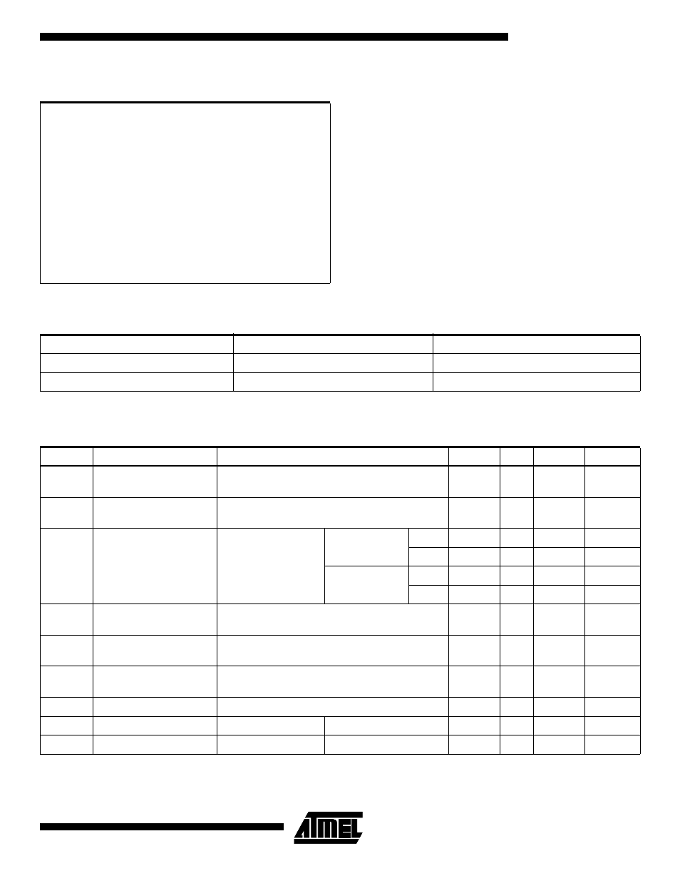
DC and AC Operating Conditions
Commercial
Industrial
Operating Temperature (Ambient)
0°C - 70°C
-40°C - 85°C
V
CC
Power Supply
2.7V - 5.5V
2.7V - 5.5V
DC Characteristics
Symbol
Parameter
Condition
Min
Typ
Max
Units
I
IL
Input or I/O
Low Leakage Current
0
≤ V
IN
≤ V
IL
(max)
-10
µA
I
IH
Input or I/O
High Leakage Current
V
IH
,min < V
IN
≤ V
CC
10
µA
I
CC1
Power Supply Current,
Standby
V
CC
= MAX,
V
IN
= 0, V
CC
ATF1500ABV
Com.
35
mA
Ind.
40
mA
ATF1500ABVL
Com.
3
mA
Ind.
5
mA
I
CC2
Power Supply Current,
Power Down Mode
V
CC
= MAX,
V
IN
= 0, V
CC
2
mA
I
OS
Output Short Circuit
Current
V
OUT
= 0.5V
-130
mA
V
IL
Input Low Voltage
V
CC
, min < V
CC
< V
CC
, max
-0.5
0.8
V
V
IH
Input High Voltage
2.0
V
CC
+ 1
V
V
OL
Output Low Voltage
V
CC
= MIN
I
OL
= 4 mA
0.45
V
V
OH
Output High Voltage
V
CC
= MIN
I
OH
= -0.1 mA
V
CC
- .2
V