Legend for table 1, Table 2. bp1 to bp4 protection code assignments – Rainbow Electronics MAX66120 User Manual
Page 5
MAX66120
ISO 15693-Compliant 1Kb Memory Fob
_______________________________________________________________________________________
5
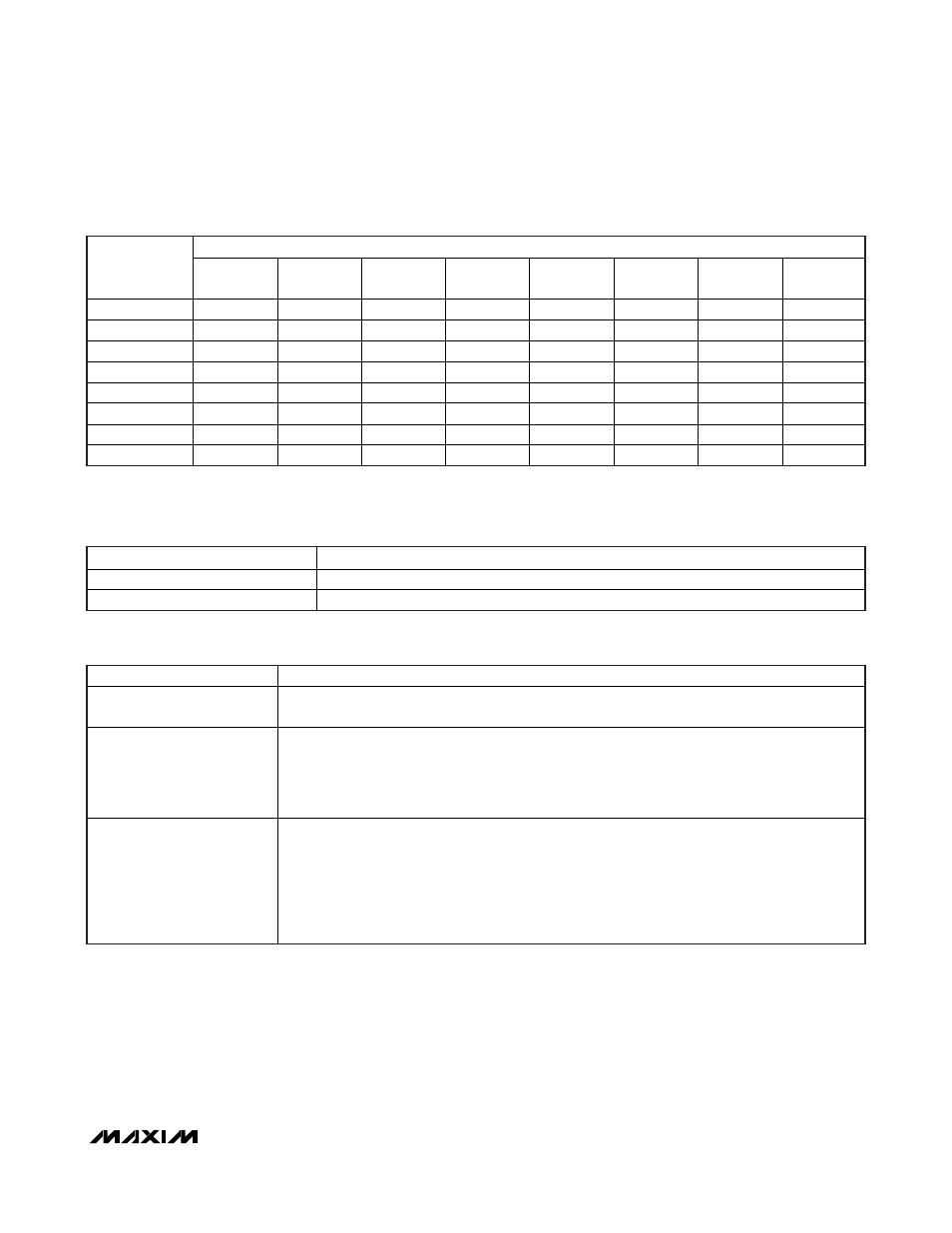
AFFECTED MEMORY AREA
CONTROLLING
REGISTER*
BLOCKS
00h TO 03h
BLOCKS
04h TO 07h
BLOCKS
08h TO 0Bh
BLOCKS
0Ch TO 0Fh
U1 TO U4
AFI
DSFID
S-LOCK
BP1 E,
W
— — — — — — —
BP2 —
E,
W
— — — — — —
BP3 — —
E,
W
— — — — —
BP4 — — —
E,
W
— — — —
U-Lock — — — — W — — —
AFI-Lock
— — — — — W — —
DSFID-Lock
— — — — — — W —
S-Lock — — — — — — — W
Table 1. Memory Protection Matrix
CODE DESCRIPTION
E ERPOM-Emulation
Mode
W Write
Protection
Legend for Table 1:
CODE DESCRIPTION
00000000b
(00h)
Unlocked (factory default)
00001010b
(0Ah)
EPROM-Emulation Mode (irreversible)
BP1: blocks 00h to 03h
BP2: blocks 04h to 07h
BP3: blocks 08h to 0Bh
BP4: blocks 0Ch to 0Fh
1010
(Axh)
Write-Protect Block Mode. Once set to Ah, the upper nibble cannot be changed to any other
value (irreversible). The bits of the lower nibble can still be changed only from 0 (unlocked) to 1
(locked) to write protect blocks individually.
b0: block 00h (BP1), block 04h (BP2), block 08h (BP3), block 0Ch (BP4)
b1: block 01h (BP1), block 05h (BP2), block 09h (BP3), block 0Dh (BP4)
b2: block 02h (BP1), block 06h (BP2), block 0Ah (BP3), block 0Eh (BP4)
b3: block 03h (BP1), block 07h (BP2), block 0Bh (BP3), block 0Fh (BP4)
Table 2. BP1 to BP4 Protection Code Assignments
*
If programmed to a locking (protecting) code, the controlling register irreversibly protects itself from further changes. See Tables 2
and 3 for additional details.
Note: Do not program the upper nibble of BP4 to 9 or 5, because this blocks the read access to blocks 0Ch to 0Fh.