Rainbow Electronics MAX66120 User Manual
Page 3
MAX66120
ISO 15693-Compliant 1Kb Memory Fob
_______________________________________________________________________________________
3
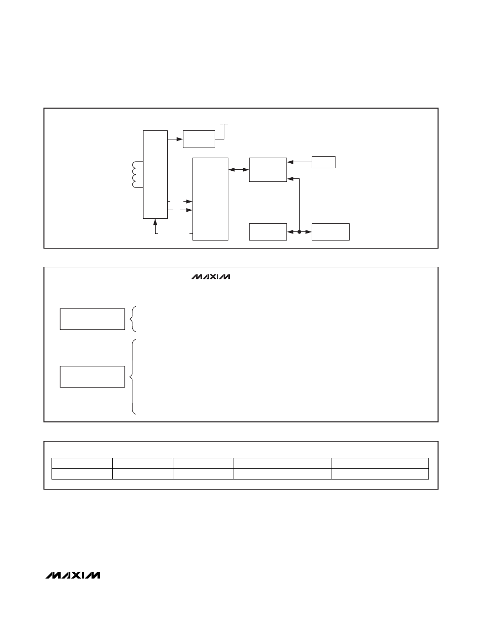
RF
FRONT-
END
VOLTAGE
REGULATOR
INTERNAL SUPPLY
MEMORY AND
FUNCTION
CONTROL
ISO 15693
FRAME
FORMATTING
AND
ERROR
DETECTION
UID
REGISTER
BLOCK
USER
EEPROM
f
c
DATA
MODULATION
Figure 1. Block Diagram
Parasite Power
As a wireless device, the MAX66120 is not connected
to any power source. It gets the energy for operation
from the surrounding RF field, which must have a mini-
mum strength as specified in the
Electrical
Characteristics
table.
Unique Identification Number (UID)
Each MAX66120 contains a factory-programmed and
locked identification number that is 64 bits long
(Figure 3). The lower 36 bits are the serial number of
the chip. The next 8 bits store the device feature
code, which is 02h. Bits 45 to 48 are 0h. The code in
AVAILABLE COMMANDS:
DATA FIELD AFFECTED:
INVENTORY
STAY QUIET
SELECT
RESET TO READY
UID, AFI, DSFID, ADMINISTRATIVE DATA
UID
UID
UID
NETWORK
FUNCTION COMMANDS
GET SYSTEM INFORMATION
WRITE SINGLE BLOCK
LOCK BLOCK
READ SINGLE BLOCK
READ MULTIPLE BLOCKS
CUSTOM READ BLOCK
WRITE AFI
LOCK AFI
WRITE DSFID
LOCK DSFID
UID, AFI, DSFID, CONSTANTS
UID, DATA OF SELECTED MEMORY BLOCK, APPLICABLE PROTECTION CONTROL REGISTER
UID, APPLICABLE PROTECTION CONTROL REGISTER
UID, SELECTED MEMORY BLOCK, APPLICABLE PROTECTION CONTROL REGISTER
UID, SELECTED MEMORY BLOCK, APPLICABLE PROTECTION CONTROL REGISTER
MFGCODE, UID, SELECTED MEMORY BLOCK, APPLICABLE PROTECTION CONTROL REGISTER,
INTEGRITY BYTES
UID, AFI BYTE
UID, AFI LOCK BYTE
UID, DSFID BYTE
UID, DSFID LOCK BYTE
MEMORY AND CONTROL
FUNCTION COMMANDS
COMMAND TYPE:
MAX66120
Figure 2. ISO 15693 Commands Overview
MSb
LSb
64
57 56
49 48
45 44
37 36
1
E0h
2Bh
0h
FEATURE CODE (02h)
36-BIT IC SERIAL NUMBER
Figure 3. 64-Bit UID