Rainbow Electronics MAX66000 User Manual
Page 4
3 bytes between SOF and EOF is called a frame
(Figure 6). The last two data characters of an ISO/IEC
14443 Type B frame are an inverted 16-bit CRC of the
preceding data characters generated according to the
CRC-16-CCITT polynomial. This CRC is transmitted with
the LSB first. For more details on the CRC-16-CCITT,
refer to ISO/IEC 14443-3, Annex B. With network func-
tion commands, the command code, parameters, and
response are embedded between SOF and CRC. With
memory function commands, command code, and
parameters are placed into the information field of
I-blocks (see the
Block Types
section), which in turn
are embedded between SOF and EOF.
For transmission, the frame information is modulated on a
carrier frequency, which is 13.56MHz for ISO/IEC 14443.
The subsequent paragraphs are a concise description
of the required modulation and coding. For full details
including SOF/EOF and subcarrier on/off timing, refer to
ISO/IEC 14443-3, Sections 7.1 and 7.2.
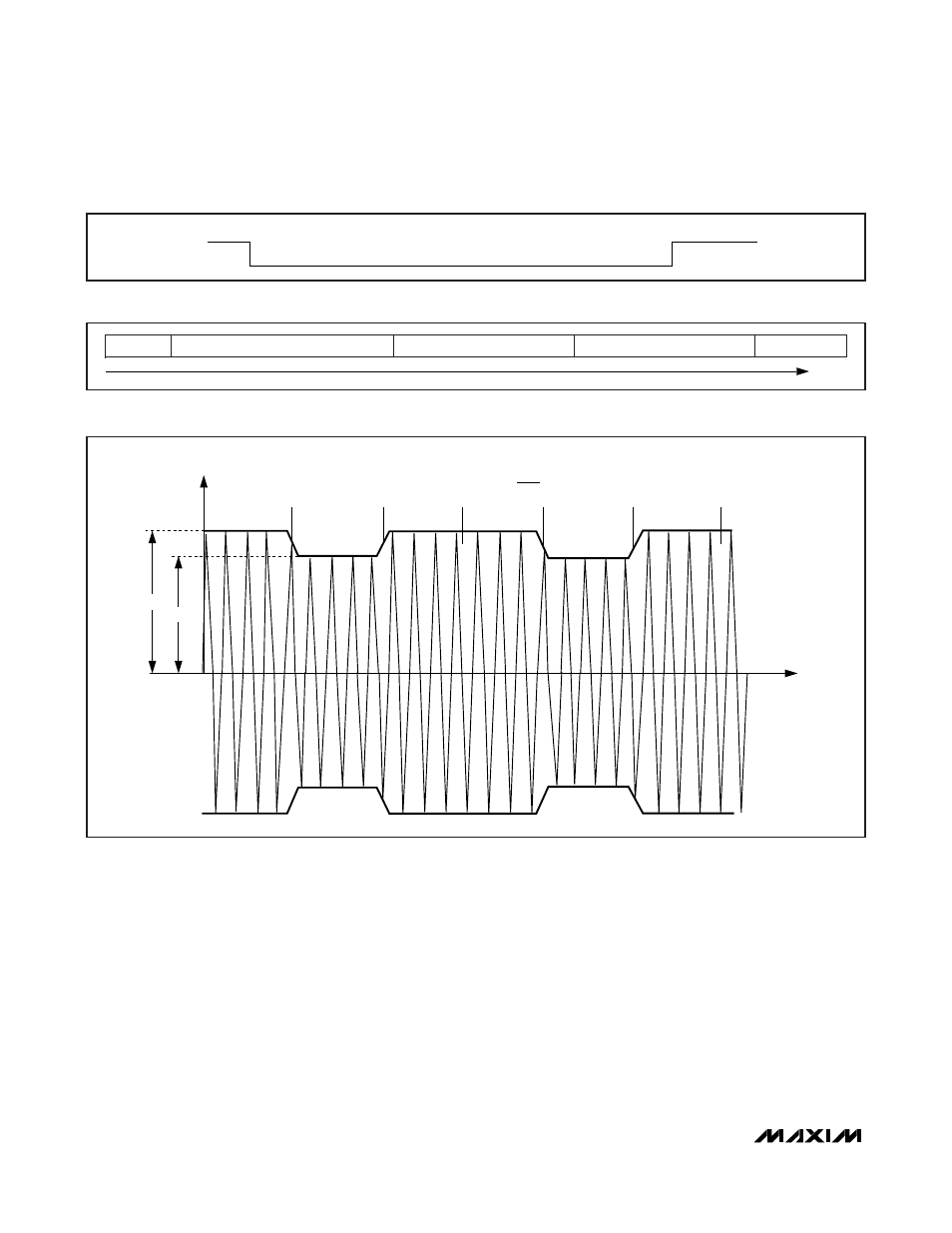
The path from master to slave uses amplitude modula-
tion with a modulation index between 8% and 14%
(Figure 7). In this direction, a START bit and logic 0 bit
correspond to a modulated carrier; STOP bit and logic
1 bit correspond to the unmodulated carrier. EOF ends
with an unmodulated carrier instead of STOP bits.
MAX66000
ISO/IEC 14443 Type B-Compliant
64-Bit UID
4
_______________________________________________________________________________________
START
1
0
BIT 1
BIT 2
BIT 3
BIT 4
BIT 5
BIT 6
BIT 7
BIT 9
STOP/IDLE
BIT 8
Figure 5. ISO/IEC 14443 SOF/EOF Character Format
SOF
ONE OR MORE DATA CHARACTERS
CRC (LSB)
CRC (MSB)
EOF
TIME
Figure 6. ISO/IEC 14443 Frame Format
A
B
CARRIER AMPLITUDE
t
1
1
1
1
0
0
MODULATION INDEX
M = = 0.08 TO 0.14
A - B
A + B
Figure 7. Downlink: 8% to 14% Amplitude Modulation