Deselect command – Rainbow Electronics MAX66000 User Manual
Page 15
MAX66000
ISO/IEC 14443 Type B-Compliant
64-Bit UID
______________________________________________________________________________________
15
Param 2 informs the slave about the data rate that shall
be used for communication in the ACTIVE state and the
maximum frame size that the master can receive.
Figure 25 shows the bit assignments for the Param 2
byte. The MAX66000 supports the data rates of
105.9kbps (code 00b), 211.9kbps (code 01b),
423.75kbps (code 10b), and 847.5kbps (code 11b).
The master can choose different data rates for request
and response. Since it does not support chaining, the
MAX66000 ignores the frame size capability and
assumes that the master can receive frames as large
as specified in the ATQB response.
The lower nibble of Param 3 is used to confirm the pro-
tocol type as specified in the lower nibble of the second
byte of the ATQB protocol info. Since ISO/IEC 14443-3
sets the upper nibble of Param 3 to 0000b, the Param 3
value to be used for the MAX66000 in the ATTRIB
request is 01h.
Param 4 assigns the slave the CID number that is used
with the block transmission protocol to address one of
several slaves in the ACTIVE state. Figure 26 shows the
Param 4 bit assignments. Since the MAX66000 sup-
ports the CID field, the master can assign any number
in the range from 0 to 14. According to ISO/IEC 14443-
3, code 15 is reserved.
The ATTRIB request frame contains one optional field,
called higher layer information (HLINF). This field can
be used to include data as in the information field of the
ISO/IEC 14443 Type B block transmission protocol (see
Figure 10). If such data is present and the slave sup-
ports the HLINF field, then the slave processes the
HLINF data and returns the result in its response to the
ATTRIB request. Typically, the ATTRIB request is trans-
mitted without HLINF field. The only HLINF data that the
MAX66000 accepts and processes is the Get UID com-
mand, code 30h.
If the ATTRIB request has a matching PUPI and a valid
CRC, the slave transmits an ATTRIB response frame, as
shown in Figure 27. The upper nibble of the indicator,
also referred to as MBLI, is 0000b, telling that the slave
does not provide any information on its internal input
buffer size; the lower nibble returns the card identifier
value that the master has just assigned to the slave.
The HL response field is optional. There are three
cases to be distinguished:
a) If there was no HLINF field in the ATTRIB request,
then there is no HL response field in the response.
b) If there was a Get UID command code (30h) in the
HLINF field of the ATTRIB request, then the HL
response field is identical to the Get UID response
information field (i.e., 00h followed by the 8-byte UID).
c) If the code in the HLINF field of the ATTRIB request
was different from 30h, then the response frame does
not contain an HL response field.
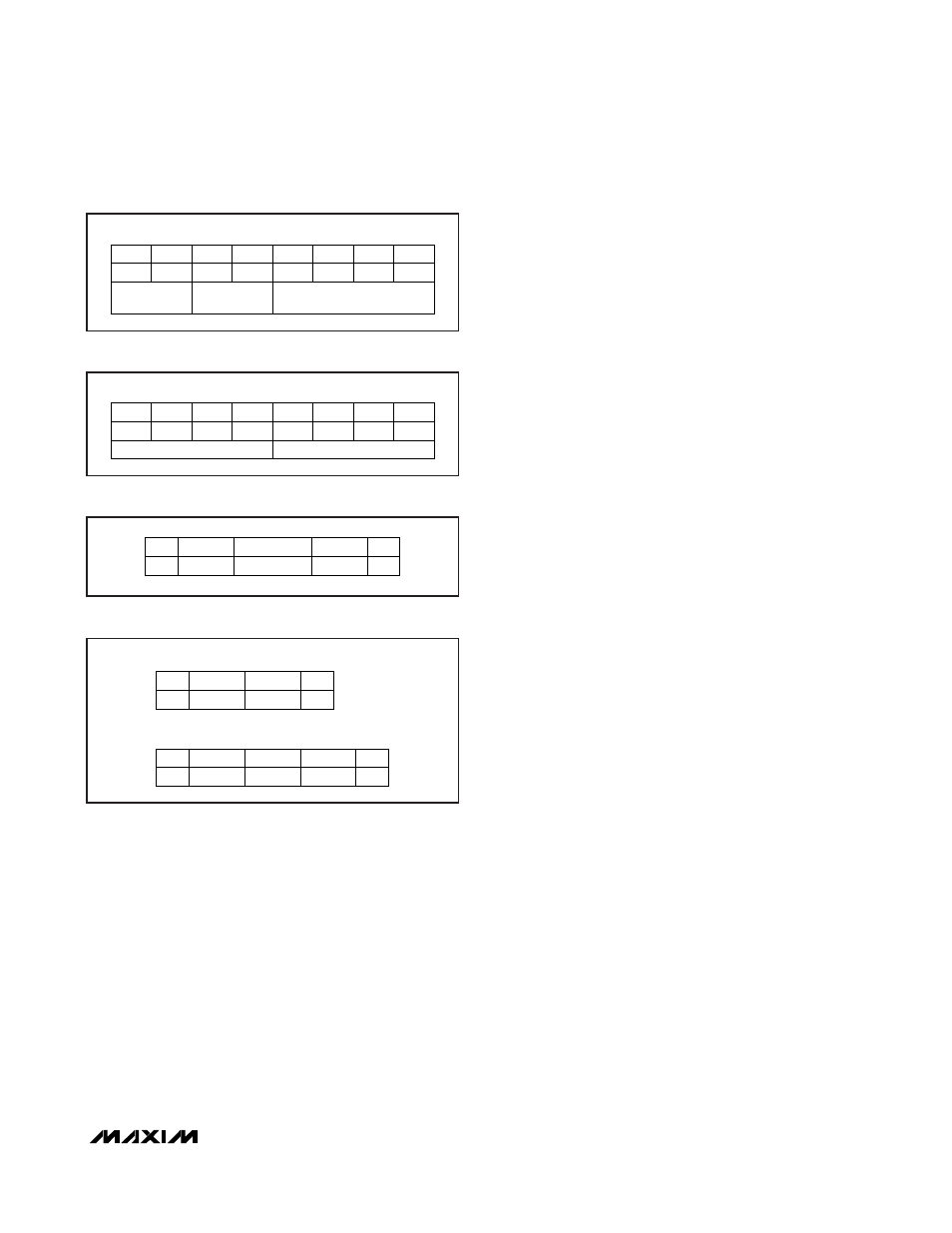
DESELECT Command
The DESELECT command is used to transition the slave
from the ACTIVE to the HALT state after the master has
completed the communication with the slave. There are
two versions of the deselect request frame, one without
CID and one with CID. Figure 28 shows both versions.
Figure 26 shows the CID format.
BIT 8
BIT 7
BIT 6
BIT 5
BIT 4
BIT 3
BIT 2
BIT 1
MSb
LSb
X
X
X
X
RESPONSE DATA
RATE (UPLINK)
RECEIVER FRAME SIZE CAPABILITY
REQUEST DATA
RATE (DOWNLINK)
Figure 25. Bit Assignments for Param 2 Byte
BIT 8
BIT 7
BIT 6
BIT 5
BIT 4
BIT 3
BIT 2
BIT 1
MSb
LSb
0
(FIXED)
CARD IDENTIFIER VALUE (CID)
0
0
0
Figure 26. Bit Assignments for Param 4 Byte
SOF
FRAME WITHOUT CID
CRC
EOF
(2 BYTES)
COMMAND
C2h
SOF
FRAME WITH CID
CRC
EOF
(2 BYTES)
CID
(1 BYTE)
COMMAND
CAh
Figure 28. DESELECT Request and Response Frames
INDICATOR
SOF
CRC
EOF
MBLI, CID
(2 BYTES)
HL RESPONSE
(
≥ 0 BYTES)
Figure 27. ATTRIB Response Frame