Network function commands, Table 2. number of slots codes – Rainbow Electronics MAX66000 User Manual
Page 12
MAX66000
ISO/IEC 14443 Type B-Compliant
64-Bit UID
12
______________________________________________________________________________________
Network Function Commands
To transition slaves devices between states, the
ISO/IEC 14443 Type B standard defines six network
function commands, called REQB, WUPB, SLOT-
MARKER, HLTB, ATTRIB, and DESELECT. The master
issues the commands in the form of request frames and
the slaves respond by transmitting response frames.
With network function commands, command code,
parameters and response are embedded between SOF
and CRC. This section describes the format of the
response and request frames and the coding of the
data fields inside the frames as detailed as necessary
to operate the MAX66000. Not all of the fields and
cases that the standard defines are relevant for the
MAX66000. For a full description of those fields refer to
the ISO/IEC 14443-3, Section 7.
REQB/WUPB Command
The REQUEST command, Type B (REQB) and the
WAKEUP command, Type B (WUPB) are the general
tools for the master to probe the RF field for the pres-
ence of slave devices and to preselect them for action
based on the value of the application family identifier
(AFI). An ISO/IEC 14443 Type B-compliant slave watch-
es for these commands while in the IDLE state,
WAITING FOR SLOT-MARKER state, and READY state.
In the HALT state, the slave only acts upon receiving a
WUPB command. The REQB or WUPB command is
transmitted as a frame, as shown in Figure 17. Besides
the command code, the request includes two parame-
ters, AFI and PARAM. The response to REQB/WUPB is
named ATQB. See the
ATQB Response
section for
details.
The ISO/IEC 14443 standard defines rules for the
assignment of the AFI codes and the behavior of the
slaves when receiving a REQB/WUPB request. If the
request specifies an AFI of 00h, a slave must process
the command regardless of its actual AFI value. If the
least significant nibble of the AFI in the request is
0000b, the slave must process the command only if the
most significant nibble of the AFI sent by the master
matches the most significant nibble of the slave’s AFI.
For all other AFI values, the slave processes the com-
mand only if the AFI in the request and the slave match.
The AFI code is factory programmed to a customer-
specific value (default is 00h) and cannot be changed.
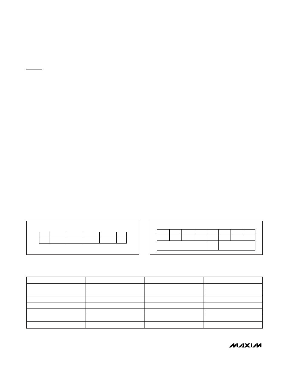
The bit assignments of the PARAM byte are shown in
Figure 18. Bits 5 to 8 are reserved and must be trans-
mitted as 0. Bit 4, if 0, indicates that the request is a
REQB command; bit 4, if 1, defines a WUPB command.
Bits 1, 2, and 3 specify the number of slots (N) to be
used in the anticollision protocol. Table 2 shows the
codes. In the case of N = 1, the SLOT-MARKER com-
mand does not apply and all slaves with a matching
AFI transition to the READY state. With multiple slaves
in the field, this leads to a data collision, since the
response frames are transmitted simultaneously. If N is
COMMAND
SOF
AFI
CRC
PARAM
EOF
05h
(1 BYTE)
(2 BYTES)
(1 BYTE)
Figure 17. REQB/WUPB Request Frame
BIT 8
BIT 7
BIT 6
BIT 5
BIT 4
REQB/
WUPB
BIT 3
BIT 2
BIT 1
MSb
LSb
0
0
0
0
(FIXED)
N
Figure 18. Bit Assignments for PARAM Byte
BIT 3
BIT 2
BIT 1
N
0 0 0 1
0 0 1 2
0 1 0 4
0 1 1 8
1 0 0 16
1 0 1
(RESERVED)
1 1 X
(RESERVED)
Table 2. Number of Slots Codes