Applications information, Table 5. clocking modes – Rainbow Electronics MAX5858 User Manual
Page 18
MAX5858
Dual, 10-Bit, 300Msps, Current-Output DAC with
4x/2x/1x Interpolation Filters
18
______________________________________________________________________________________
The MAX5858 can also operate in an interleave data
mode. Pulling IDE high activates this mode. In inter-
leave mode, data for both DAC channels is written
through input port A. Channel B data is written on the
falling edge of the CLK signal and then channel A data
is written on the following rising edge of the CLK signal.
Both DAC outputs (channel A and B) are updated
simultaneously on the next following rising edge of the
CLK. In interleave data mode, the maximum input data
rate per channel is half of the rate in noninterleave
mode. The interleave data mode is attractive in applica-
tions where lower data rates are acceptable and inter-
facing on a single 10-bit bus is desired (Figure 7).
Applications Information
Differential-to-Single-Ended Conversion
The MAX5858 exhibits excellent dynamic performance
to synthesize a wide variety of modulation schemes,
including high-order QAM modulation with OFDM.
Figure 8 shows a typical application circuit with output
transformers performing the required differential-to-sin-
gle-ended signal conversion. In this configuration, the
MAX5858 operates in differential mode, which reduces
even-order harmonics, and increases the available out-
put power.
F2EN
F1EN
DIFFERENTIAL CLOCK
FREQUENCY (f
CLKDIFF)
(MHz)
CLK OUTPUT
(MHz)
DAC RATE
(f
DAC
)
INTERPOLATION
MAX SIGNAL
BANDWIDTH (MHz)
0
0
0 to 165
F
CLKDIFF
f
CLKDIFF
1x
82
0
1
0 to 300
F
CLKDIFF
/2
f
CLKDIFF
2x
63
1
1
0 to 300
f
CLKDIFF
/4
f
CLKDIFF
4x
31
1
0
Illegal
Table 5. Clocking Modes
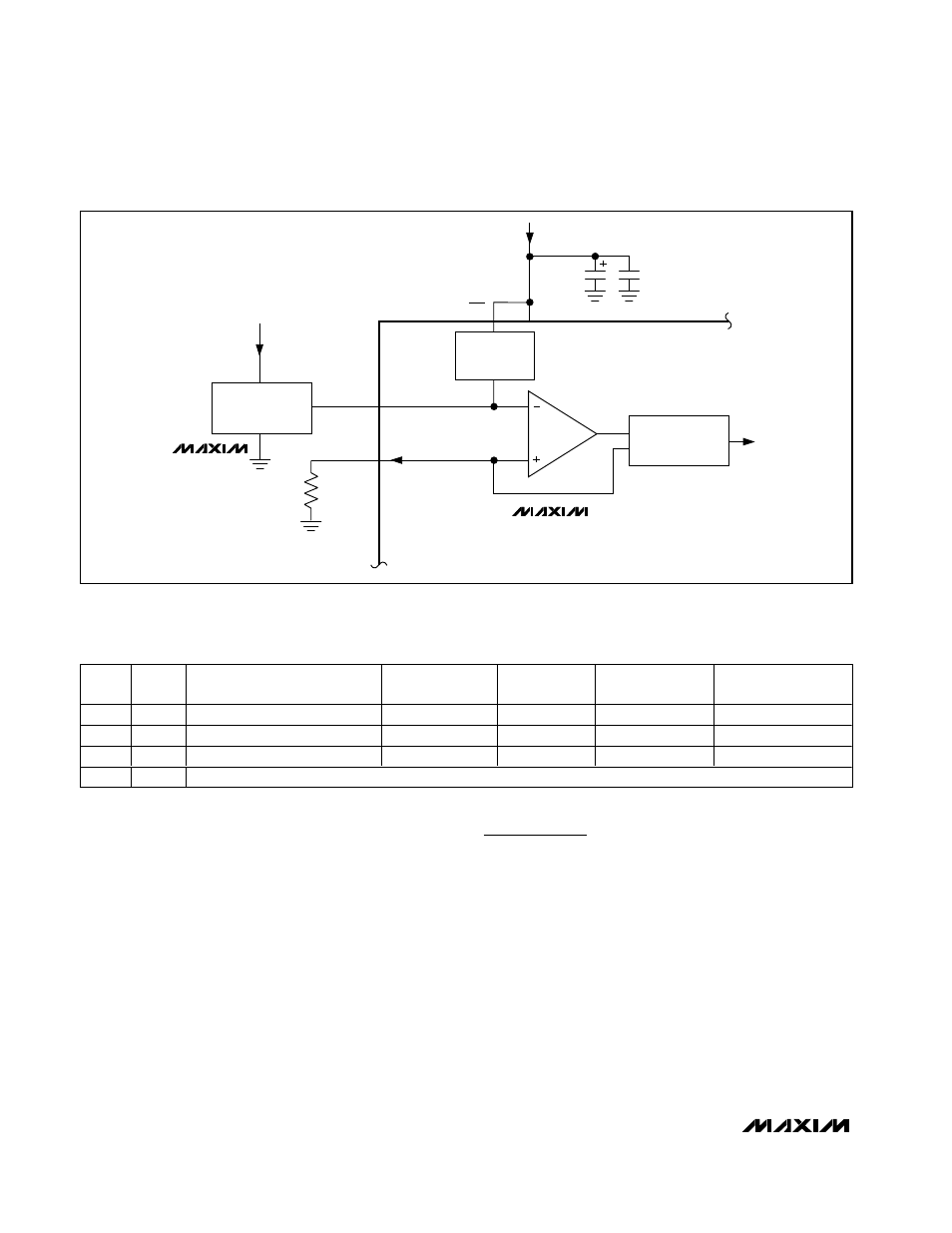
I
FS
0.1
µF
10
µF
AV
DD
R
SET
I
REF
REFR
AV
DD
REFO
1.24V
BANDGAP
REFERENCE
CURRENT-
SOURCE ARRAY
EXTERNAL
+1.24V
REFERENCE
REN
MAX5858
MAX6520
AGND
AGND
AGND
Figure 5. MAX5858 with External Reference