Max7313, Table 12. pwm intensity settings (blink enabled) – Rainbow Electronics MAX7313 User Manual
Page 20
MAX7313
Using PWM Intensity Controls with Blink Disabled
When blink is disabled (Table 7), the blink phase 0 reg-
isters specify each output’s logic level during the PWM
on-time (Table 8). The effect of setting an output’s blink
phase 0 register bit to 0 or 1 is shown in Table 11. With
its output bit set to zero, an LED can be controlled with
16 intensity settings from 1/16th duty through fully on,
but cannot be turned fully off using the PWM intensity
control. With its output bit set to 1, an LED can be con-
trolled with 16 intensity settings from fully off through
15/16th duty.
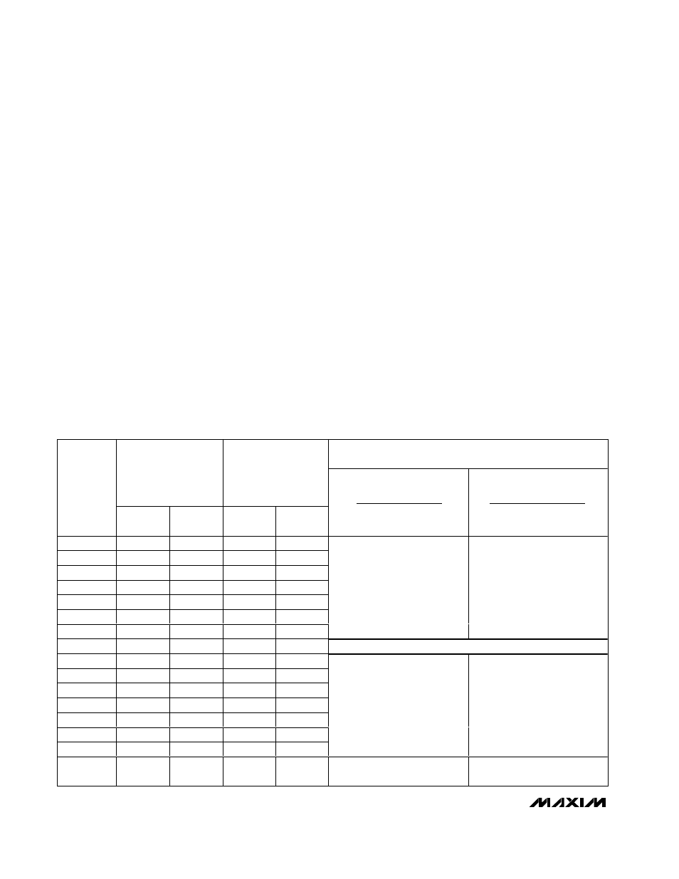
Using PWM Intensity Controls with Blink Enabled
When blink is enabled (Table 7), the blink phase 0 regis-
ters and blink phase 1 registers specify each output’s
logic level during the PWM on-time during the respective
blink phases (Tables 8 and 9). The effect of setting an
output’s blink phase x register bit to 0 or 1 is shown in
Table 12. LEDs can be flipped between either directly on
and off, or between a variety of high/low PWM intensities.
Global/O16 Intensity Control
The 4 bits used for output O16’s PWM individual inten-
sity setting also double as the global intensity control
(Table 13). Global intensity simplifies the PWM settings
when the application requires them all to be the same,
such as for backlight applications, by replacing the 17
individual settings with 1 setting. Global intensity is
enabled with the Global Intensity flag G in the configu-
ration register (Table 4). When global PWM control is
used, the 4 bits of master intensity and 4 bits of global
intensity effectively combine to provide an 8 bit, 240-
step intensity control applying to all outputs.
It is not possible to apply global PWM control to a sub-
set of the ports, and use the others as logic outputs. To
mix static logic outputs and PWM outputs, individual
PWM control must be selected (Table 10).
16-Port I/O Expander with LED Intensity
Control and Interrupt
20
______________________________________________________________________________________
Table 12. PWM Intensity Settings (Blink Enabled)
EXAMPLES OF LED BLINK BEHAVIOR
(LED IS ON WHEN OUTPUT IS LOW)
PWM DUTY CYCLE
OUTPUT BLINK
PHASE X
REGISTER BIT = 0
PWM DUTY CYCLE
OUTPUT BLINK
PHASE X
REGISTER BIT = 1
OUTPUT
(OR
GLOBAL)
INTENSITY
SETTING
LOW
TIME
HIGH
TIME
LOW
TIME
HIGH
TIME
BLINK PHASE 0
REGISTER BIT = 0
BLINK PHASE 1
REGISTER BIT = 1
BLINK PHASE 0
REGISTER BIT = 1
BLINK PHASE 1
REGISTER BIT = 0
0x0
1/16
15/16
15/16
1/16
0x1
2/16
14/16
14/16
2/16
0x2
3/16
13/16
13/16
3/16
0x3
4/16
12/16
12/16
4/16
0x4
5/16
11/16
11/16
5/16
0x5
6/16
10/16
10/16
6/16
0x6
7/16
9/16
9/16
7/16
P hase 0: LE D on at l ow i ntensi ty
P hase 1: LE D on at hi g h i ntensi ty
P hase 0: LE D on at hi g h i ntensi ty
P hase 1: LE D on at l ow i ntensi ty
0x7
8/16
8/16
8/16
8/16
Output is half intensity during both blink phases
0x8
9/16
7/16
7/16
9/16
0x9
10/16
6/16
6/16
10/16
0xA
11/16
5/16
5/16
11/16
0xB
12/16
4/16
4/16
12/16
0xC
13/16
3/16
3/16
13/16
0xD
14/16
2/16
2/16
14/16
0xE
15/16
1/16
1/16
15/16
P hase 0: LE D on at hi g h i ntensi ty
P hase 1: LE D on at l ow i ntensi ty
P hase 0: LE D on at l ow i ntensi ty
P hase 1: LE D on at hi g h i ntensi ty
0xF
Static low
Static low
Static high
impedance
Static high
impedance
Phase 0: LED on continuously
Phase 1: LED off continuously
Phase 0: LED off continuously
Phase 1: LED on continuously