Table 8. blink phase 0 registers, Table 9. blink phase 1 registers – Rainbow Electronics MAX7313 User Manual
Page 17
Blink Phase Registers
When the blink function is disabled, the two blink phase
0 registers set the logic levels of the 16 ports (P0
through P15) when configured as outputs (Table 8). A
duplicate pair of registers called the blink phase 1 reg-
isters are also used if the blink function is enabled (Table
9). A logic high sets the appropriate output port high
impedance, while a logic low makes the port go low.
Reading a blink phase register reads the value stored
in the register, not the actual port condition. The port
output itself may or may not be at a valid logic level,
depending on the external load connected.
The 17th output, O16, is controlled through 2 bits in the
configuration register, which provide the same static or
blink control as the other 16 output ports.
PWM Intensity Control
The MAX7313 includes an internal oscillator, nominally
32kHz, to generate PWM timing for LED intensity con-
trol or other applications such as PWM trim DACs.
PWM can be disabled entirely for all the outputs. In this
case, all outputs are static and the MAX7313 operating
current is lowest because the internal PWM oscillator is
turned off.
The MAX7313 can be configured to provide any combi-
nation of PWM outputs and glitch-free logic outputs.
Each PWM output has an individual 4-bit intensity con-
trol (Table 14). When all outputs are to be used with the
same PWM setting, the outputs can be controlled
together instead using the global intensity control
(Table 13). Table 10 shows how to set up the MAX7313
to suit a particular application.
PWM Timing
The PWM control uses a 240-step PWM period, divided
into 15 master intensity timeslots. Each master intensity
timeslot is divided further into 16 PWM cycles (Figure 11).
The master intensity operates as a gate, allowing the indi-
vidual output settings to be enabled from 1 to 15 timeslots
per PWM period (Figures 12, 13, 14) (Table 13).
Each output’s individual 4-bit intensity control only
operates during the number of timeslots gated by the
master intensity. The individual controls provide 16
intensity settings from 1/16 through 16/16 (Table 14).
Figures 15, 16, and 17 show examples of individual
intensity control settings. The highest value an individ-
ual or global setting can be set to is 16/16. This setting
forces the output to ignore the master control, and fol-
low the logic level set by the appropriate blink phase
register bit. The output becomes a glitch-free static out-
put with no PWM.
MAX7313
16-Port I/O Expander with LED Intensity
Control and Interrupt
______________________________________________________________________________________
17
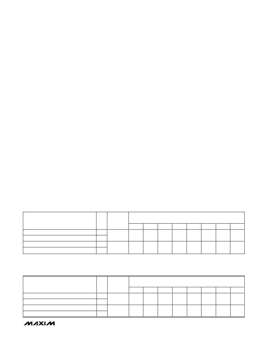
Table 8. Blink Phase 0 Registers
REGISTER DATA
REGISTER
R/
W
ADDRESS
CODE
(HEX)
D7
D6
D5
D4
D3
D2
D1
D0
Write outputs P7–P0 phase 0
0
Read back outputs P7–P0 phase 0
1
0x02
OP7
OP6
OP5
OP4
OP3
OP2
OP1
OP0
Write outputs P15–P8 phase 0
0
Read back outputs P15–P8 phase 0
1
0x03
OP15
OP14
OP13
OP12
OP11
OP10
OP9
OP8
Table 9. Blink Phase 1 Registers
REGISTER DATA
REGISTER
R/
W
ADDRESS
CODE
(HEX)
D7
D6
D5
D4
D3
D2
D1
D0
Write outputs P7–P0 phase 1
0
Read back outputs P7–P0 phase 1
1
0x0A
OP7
OP6
OP5
OP4
OP3
OP2
OP1
OP0
Write outputs P15–P8 phase 0
0
Read back outputs P15–P8 phase 1
1
0x03
OP15
OP14
OP13
OP12
OP11
OP10
OP9
OP8