Rainbow Electronics MAX6975 User Manual
Page 13
Setting configuration bit D0 to 1 enables multiplex
operation.
MUX0 and MUX1 alternate the LED anode
drive voltage between two sets of LEDs. The R, G, and
B ports provide individual PWM control during alternate
MUX cycles as shown in
Figure
3. The alternating MUX
cycles reduce the global-intensity resolution (the num-
ber of subframes) by half, which reduces the average
LED current by half.
Watchdog
A selectable watchdog timer monitors serial-interface
inputs CLKI, DIN, and LOADI. Enabling the watchdog
timer requires that CLKI, DIN, and LOADI toggle at
least once every 40ms. If any of these transitions fails to
occur, then the individual-intensity PWM data latches
clear. This condition effectively blanks the LEDs.
Update the individual-intensity PWM data registers to
turn the LEDs back on. The watchdog timeout does not
affect the calibration or global-intensity data, the clock
synchronization, or multiplexed/nonmultiplexed setting.
Use the watchdog functionality in safety-critical appli-
cations where a blanked display is safer than an incor-
rect display.
LED Open-Circuit and
Overtemperature Detection
The MAX6974/MAX6975 feature two fault detection func-
tions: open-circuit LED outputs and overtemperature. An
LED open circuit is detected on driver outputs by moni-
toring for output voltages below 200mV. When an open
circuit is detected, the MAX6974/MAX6975 increments
a fault counter included in the serial-interface protocol
that can be routed back to the host transmitter for diag-
nostics. Any number of open-circuit LEDS, multiplexed
or nonmultiplexed, can be detected, however, only one
counter increment occurs per device.
The MAX6974/MAX6975 detect die temperatures
above T
DIE
= +165°C and disable all output drivers by
setting all PWM data to zero. The fault counter in the
serial-interface protocol is incremented by one count
for each cascaded device with an overtemperature
condition. The output drivers are turned back on when
the die temperature falls below T
DIE
= +150°C. The
fault counter value is distinguished between LED open-
circuit and overtemperature conditions by the serial-
interface command used at the time of detection (see
the
Serial Interface section for more details).
MAX6974/MAX6975
24-Output PWM LED Drivers
for Message Boards
______________________________________________________________________________________
13
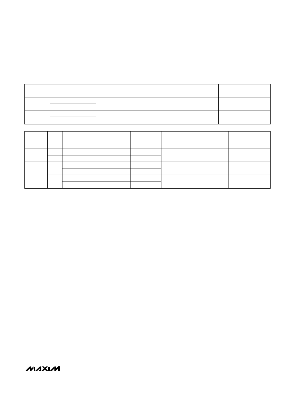
PART
MUX
BIT
OPERATION
PWM
RES.
TOTAL CLOCKS PER
PWM SUBFRAME
USEABLE CLOCKS PER
PWM SUBFRAME
MAXIMUM PWM
DUTY CYCLE
0
Nonmultiplex
MAX6974
1
Multiplex
12 bits
4096
4064
4064 / 4096 = 99.22%
0
Nonmultiplex
MAX6975
1
Multiplex
14 bits
16,384
16,320
16,320 / 16,384 = 99.61%
Table 3. MAX6974/MAX6975 Timing Comparison
PART
GLB4
BIT
MUX
BIT
OPERATION
GLOBAL
PDM
RES.
SUBFRAMES
PER FRAME
CLOCKS
PER
FRAME
CLOCK
FREQUENCY (MHz)
FOR 50fps
CLOCK
FREQUENCY (MHz)
FOR 60fps
X
0
Nonmultiplex
7 bits
128
MAX6974
X
1
Multiplex
6 bits
64
524,288
26.2144
31.45728
0
Nonmultiplex
5 bits
32
0
1
Multiplex
4 bits
16
524,288
26.2144
31.45728
0
Nonmultiplex
3 bits
8
MAX6975
1
1
Multiplex
2 bits
4
131,072
6.5536
7.8643