Rainbow Electronics MAX9755 User Manual
Page 19
MAX9750/MAX9751/MAX9755
2.6W Stereo Audio Power Amplifiers and
DirectDrive Headphone Amplifiers
______________________________________________________________________________________
19
Headphone Amplifier
In conventional single-supply headphone amplifiers,
the output-coupling capacitor is a major contributor of
audible clicks and pops. Upon startup, the amplifier
charges the coupling capacitor to its bias voltage, typi-
cally half the supply. Likewise, during shutdown, the
capacitor is discharged to GND. A DC shift across the
capacitor results, which in turn appears as an audible
transient at the speaker. Since the MAX9750/MAX9751/
MAX9755 do not require output-coupling capacitors, no
audible transient occurs.
Additionally, the MAX9750/MAX9751/MAX9755 features
extensive click-and-pop suppression that eliminates
any audible transient sources internal to the device.
The Power-Up/Down Waveform in the Typical
Operating Characteristics shows that there are minimal
spectral components in the audible range at the output
upon startup and shutdown.
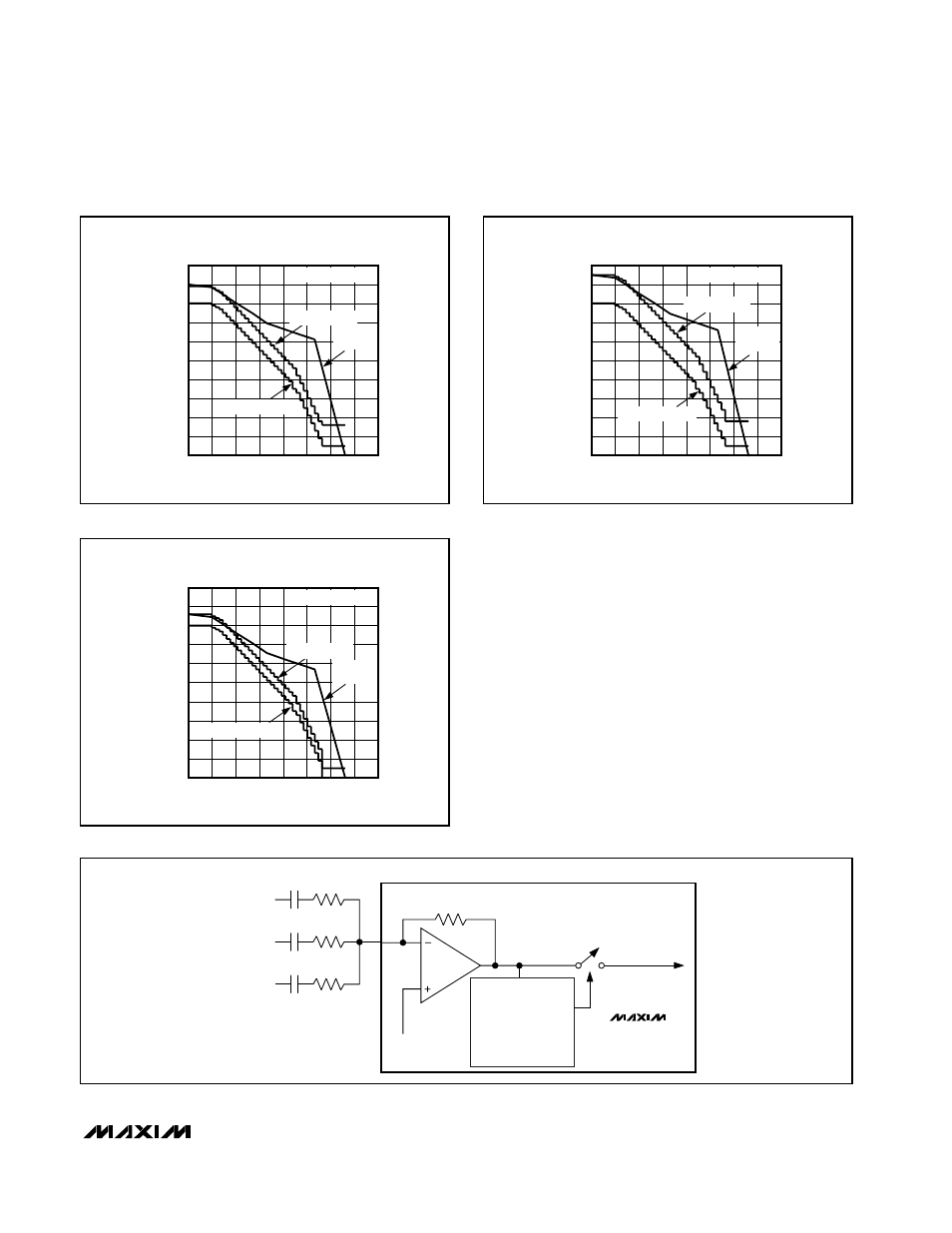
Figure 7a. Volume Control Transfer Function
-80
-60
-70
-40
-50
-20
-30
-10
10
0
20
0
1.0
1.5
0.5
2.0
2.5
3.0
3.5
4.0
MAX9750A
VOLUME CONTROL TRANSFER FUNCTION
V
VOL
(V)
GAIN (dB)
AUDIO
TAPER POT
GAIN1 = GAIN2 = 0
SPEAKER MODE
HEADPHONE MODE
Figure 7b. Volume Control Transfer Function
-80
-60
-70
-40
-50
-20
-30
-10
10
0
20
0
1.0
1.5
0.5
2.0
2.5
3.0
3.5
4.0
MAX9750B
VOLUME CONTROL TRANSFER FUNCTION
V
VOL
(V)
GAIN (dB)
AUDIO
TAPER POT
GAIN1 = GAIN2 = 0
SPEAKER MODE
HEADPHONE MODE
Figure 7c. Volume Control Transfer Function
-80
-60
-70
-40
-50
-20
-30
-10
10
0
20
0
1.0
1.5
0.5
2.0
2.5
3.0
3.5
4.0
MAX9750C
VOLUME CONTROL TRANSFER FUNCTION
V
VOL
(V)
GAIN (dB)
AUDIO
TAPER POT
GAIN1 = GAIN2 = 0
SPEAKER MODE
HEADPHONE MODE
MAX9750
R
S3
47kΩ
BEEP
0.47µF
SOURCE 3
R
S2
47kΩ
0.47µF
SOURCE 2
R
S1
47kΩ
0.47µF
SOURCE 1
R
INT
47kΩ
BIAS
WINDOW
DETECTOR
(0.3V
P-P
THRESHOLD)
FREQUENCY
DETECTOR
(300Hz THRESHOLD)
SPEAKER/HEADPHONE
AMPLIFER INPUTS
V
OUT(BEEP)
Figure 8. Beep Input